Multi-shafting servo system synchronous control method based on dynamic error coefficient
A dynamic error and servo system technology, applied in the direction of adaptive control, general control system, control/adjustment system, etc., can solve the problems of complex control method design, poor tracking dynamic signal performance, large synchronization error, etc.
- Summary
- Abstract
- Description
- Claims
- Application Information
AI Technical Summary
Problems solved by technology
Method used
Image

Examples
specific Embodiment approach
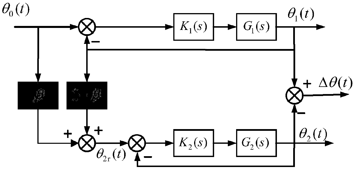
[0058] Specific implementation methods: such as Figures 1 to 6 As shown, the implementation process of the multi-axis servo system synchronization control method based on the dynamic error coefficient described in this embodiment is as follows:
[0059] The core of the multi-axis synchronous control method based on the dynamic error coefficient method is to construct the reference command signal of the fast-changing axis by solving the dynamic error coefficient of each axis. The pull-type expression of a shaft output signal in a multi-axis servo system is
[0060]
[0061] in, is the closed-loop transfer function, and R(s) is the input reference command signal, then the Expand in the form of Taylor series in the neighborhood of s=0
[0062]
[0063] in,
[0064]
[0065] Available,
[0066] Y(s)=C 0 R(s)+C 1 sR(s)+C 2 the s 2 R(s)+...+C n the s n R(s)
[0067] Through the inverse Laplace transform of Y(s), the dynamic process expression of the output si...
Embodiment 1
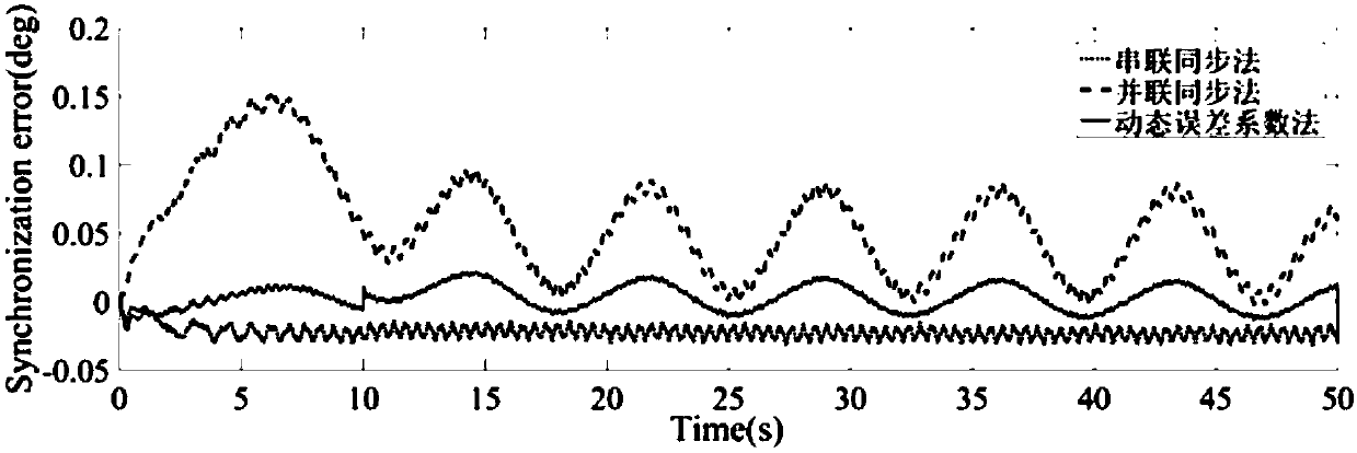
[0077] Embodiment 1: In step 2, adopt the method of scheme 1 to obtain the dynamic error coefficient, and then obtain the dynamic structure coefficient β, and verify the synchronous control effect. The process of obtaining the dynamic error coefficient by using the input and output of the multi-axis servo system is as follows:
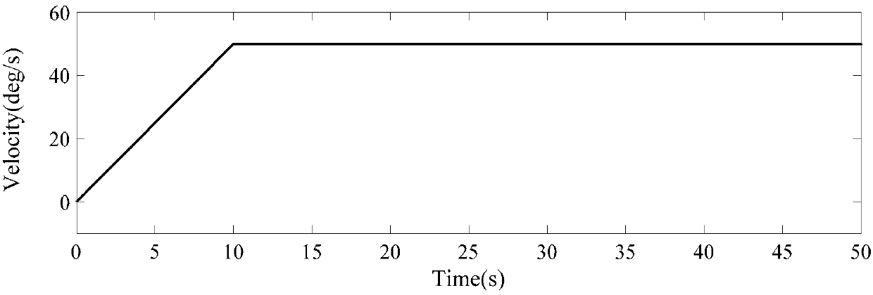
[0078] The first step is to set the appropriate input signal to obtain the expression of the dynamic output of the two shafts of the two-axis speed servo system; first, input the same command for the fast-changing shaft and the slow-changing shaft of the two-axis speed servo system respectively signal, the speed change form of the command signal is acceleration first and then constant speed; obtain the real-time change data of the angular position of the input command, the real-time change data of the angular velocity, the real-time change data of the angular acceleration and the real-time change data of the angular position output; according to the dyn...
Embodiment 2
[0093] Embodiment 2: In step 2, the process of using the multi-axis servo system identification model to obtain the dynamic error coefficient is:
[0094] The first step is to identify the mathematical model of each axis of the dual-axis speed servo system;
[0095] Test the frequency characteristics of the object on the dual-axis rate servo system, and apply the least squares method to the measured FFT amplitude ratio and FFT phase angle difference to fit the object model. The mathematical model of the slowly variable axis system is G 1 (s), the mathematical model of the fast-changing shaft system is G 2 (s);
[0096] The second step is to design the controller;
[0097] According to the system requirements, the controller in the synchronous control structure is designed, and the controller of the slowly variable shaft system is K 1 (s), the controller of the fast-changing shaft system is K 2 (s);
[0098] The third step is to find the dynamic error coefficient C 1i , i...
PUM
 Abstract
Description
Claims
Application Information
 - R&D
- Intellectual Property
- Life Sciences
- Materials
- Tech Scout
- Unparalleled Data Quality
- Higher Quality Content
- 60% Fewer Hallucinations
Browse by: Latest US Patents, China's latest patents, Technical Efficacy Thesaurus, Application Domain, Technology Topic, Popular Technical Reports.
© 2025 PatSnap. All rights reserved.Legal|Privacy policy|Modern Slavery Act Transparency Statement|Sitemap|About US| Contact US: help@patsnap.com