Method and device for estimating angle and angular velocity of holder motor, holder, and aircraft

An angular velocity and angle technology, applied in the direction of electric speed/acceleration control, etc., can solve the problems of inability to obtain accurate motor angular velocity, single data type, and inability to obtain accurate angular velocity

Inactive Publication Date: 2018-11-06
SHENZHEN AUTEL INTELLIGENT AVIATION TECH CO LTD
View PDF5 Cites 24 Cited by
  • Summary
  • Abstract
  • Description
  • Claims
  • Application Information

AI Technical Summary

Problems solved by technology

[0004] In the process of realizing the present invention, the inventor found that there are at least the following problems in the related art: 1. There is an obvious cost disadvantage in adopting the angle sensor
Since the pan/tilt of the UAV is usually a multi-axis pan/tilt, and for multiple motors in the multi-axis pan/tilt, multiple angle sensors need to be configured to obtain the angle and angular velocity of the corresponding motor, which increases the cost of the collected measurement information
2. The data type provided by the angle sensor is single, and the acc

Method used


Image

  • Method and device for estimating angle and angular velocity of holder motor, holder, and aircraft
  • Method and device for estimating angle and angular velocity of holder motor, holder, and aircraft
  • Method and device for estimating angle and angular velocity of holder motor, holder, and aircraft

Examples


Embodiment 1

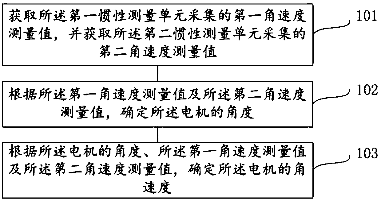
[0098] figure 1 It is a schematic flowchart of a method for estimating the angle and angular velocity of a pan-tilt motor provided by an embodiment of the present invention. Wherein, the method for estimating the angle and angular velocity of the pan-tilt motor can be executed by various controllers with certain logic processing capabilities, such as pan-tilt controllers. The pan-tilt controller can be applied to an aircraft, for example, an unmanned aerial vehicle. In the following, the controller implementing the gimbal motor angle and angular velocity estimation method will be described using the gimbal controller as an example, and the aircraft as an unmanned aerial vehicle. Among them, the UAV includes a camera component. The camera component includes a pan-tilt and a shooting device mounted on the pan-tilt. The pan-tilt includes a base, a motor, a pan-tilt controller and an electric regulator. The ESC is electrically connected to the motor, and the ESC is used to contr...

Embodiment 2

[0152] Figure 5It is a schematic diagram of a pan-tilt motor angle and angular velocity estimation device provided by an embodiment of the present invention. Wherein, the pan-tilt motor angle and angular velocity estimating device 50 can be configured in various controllers with certain logic processing capabilities, such as pan-tilt controllers. The pan-tilt controller can be applied to an aircraft, for example, an unmanned aerial vehicle. In the following, the gimbal motor angle and angular velocity estimating device 50 is configured in the gimbal controller as an example, and the aircraft is an unmanned aerial vehicle as an example for illustration. Among them, the UAV includes a camera component. The camera component includes a pan-tilt and a shooting device mounted on the pan-tilt. The pan-tilt includes a base, a motor, a pan-tilt controller and an electric regulator. The ESC is electrically connected to the motor, and the ESC is used to control the motor. Moreover, t...

Embodiment 3

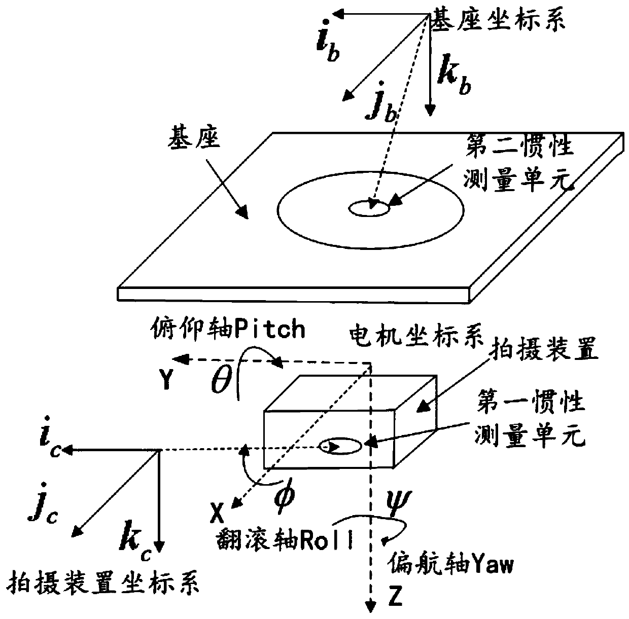
[0200] Image 6 A cloud platform provided by an embodiment of the present invention. Described cloud platform 60 is used for carrying photographing device, and described cloud platform 60 comprises: base 601 and motor 602, described photographing device and described base 601 are connected through described motor 602, and described photographing device is provided with the first An inertial measurement unit, the base 601 is provided with a second inertial measurement unit.

[0201] The cloud platform 60 further includes: at least one processor 603 and a memory 604 communicatively connected with the at least one processor 603 . Wherein, at least one processor 603 is connected with the motor 602 . Figure 7 A processor 603 is taken as an example.

[0202] The processor 603 and the memory 604 may be connected via a bus or in other ways, Figure 7 Take connection via bus as an example.

[0203] The memory 604, as a non-volatile computer-readable storage medium, can be used to...


PUM


Abstract

Embodiments of the invention relate to the technical field of aircrafts, and disclose a method and device for estimating angle and angular velocity of a holder motor, a holder, a photographing assembly, and an aircraft. The holder is used for carrying a photographing device. The holder includes a base and a motor. The photographing device is connected with the base through the motor. The photographing device is provided with a first inertia measurement unit, and the base is provided with a second inertia measurement unit. The method includes the steps: acquiring a first angular velocity measurement value collected by the first inertia measurement unit, and acquiring a second angular velocity measurement value collected by the second inertia measurement unit; determining the angle of the motor according to the first angular velocity measurement value and the second angular velocity measurement value; determining the angular velocity of the motor based on the angle of the motor, the first angular velocity measurement value, and the second angular velocity measurement value. The method can reduce the cost in obtaining the angle and angular velocity of the holder motor, and effectivelyimproves the estimation accuracy of the angle and angular velocity of the holder motor.

Description

technical field [0001] Embodiments of the present invention relate to the technical field of aircraft, in particular to a method for estimating the angle and angular velocity of a pan-tilt motor, a device for estimating the angle and angular velocity of a pan-tilt motor, a pan-tilt, and a camera assembly with the camera assembly, and an aircraft with the camera assembly . Background technique [0002] At present, aircrafts, for example, unmanned aerial vehicles (Unmanned Aerial Vehicle, UAV), also known as unmanned aerial vehicles, have been more and more widely used. UAV is a new concept equipment in rapid development, which has the advantages of small size, light weight, flexible maneuvering, quick response, unmanned driving, and low operation requirements. The UAV is equipped with various types of shooting devices through the gimbal, such as cameras, video cameras, etc., which can realize real-time image transmission and detection of high-risk areas. It is a powerful sup...

Claims


Application Information

Patent Timeline
IPC IPC(8): G05D13/62
CPCG05D13/62
Inventor 徐运扬
Owner SHENZHEN AUTEL INTELLIGENT AVIATION TECH CO LTD
Why Eureka
Try Eureka