
Method and device for establishing finite element model of power transmission tower

A technology for model building and transmission towers, applied in electrical digital data processing, special data processing applications, instruments, etc.

Active Publication Date: 2018-11-06
ELECTRIC POWER RES INST OF GUANGDONG POWER GRID
View PDF4 Cites 7 Cited by
  • Summary
  • Abstract
  • Description
  • Claims
  • Application Information

AI Technical Summary

Problems solved by technology

[0004] The invention provides a method and device for establishing a finite element model of a transmission tower. The method can quickly and correctly determine the cross-sectional direction of the angle steel member, ensure that the model is closer to the prototype, and can solve the problem that the traditional modeling technology cannot quickly and correctly determine the angle steel member. Technical issues of cross-sectional orientation

Method used


Image

  • Method and device for establishing finite element model of power transmission tower
  • Method and device for establishing finite element model of power transmission tower
  • Method and device for establishing finite element model of power transmission tower

Examples


Embodiment Construction

[0053] The invention provides a method and device for establishing a finite element model of a transmission tower. The method can quickly and correctly determine the cross-sectional direction of the angle steel member, ensure that the model is closer to the prototype, and can solve the problem that the traditional modeling technology cannot quickly and correctly determine the angle steel member. The technical problem of the cross-sectional orientation.

[0054] In order to make the purpose, features and advantages of the present invention more obvious and understandable, the technical solutions in the embodiments of the present invention will be clearly and completely described below in conjunction with the accompanying drawings in the embodiments of the present invention. Obviously, the following The described embodiments are only some, not all, embodiments of the present invention. Based on the embodiments of the present invention, all other embodiments obtained by persons o...


PUM


Abstract

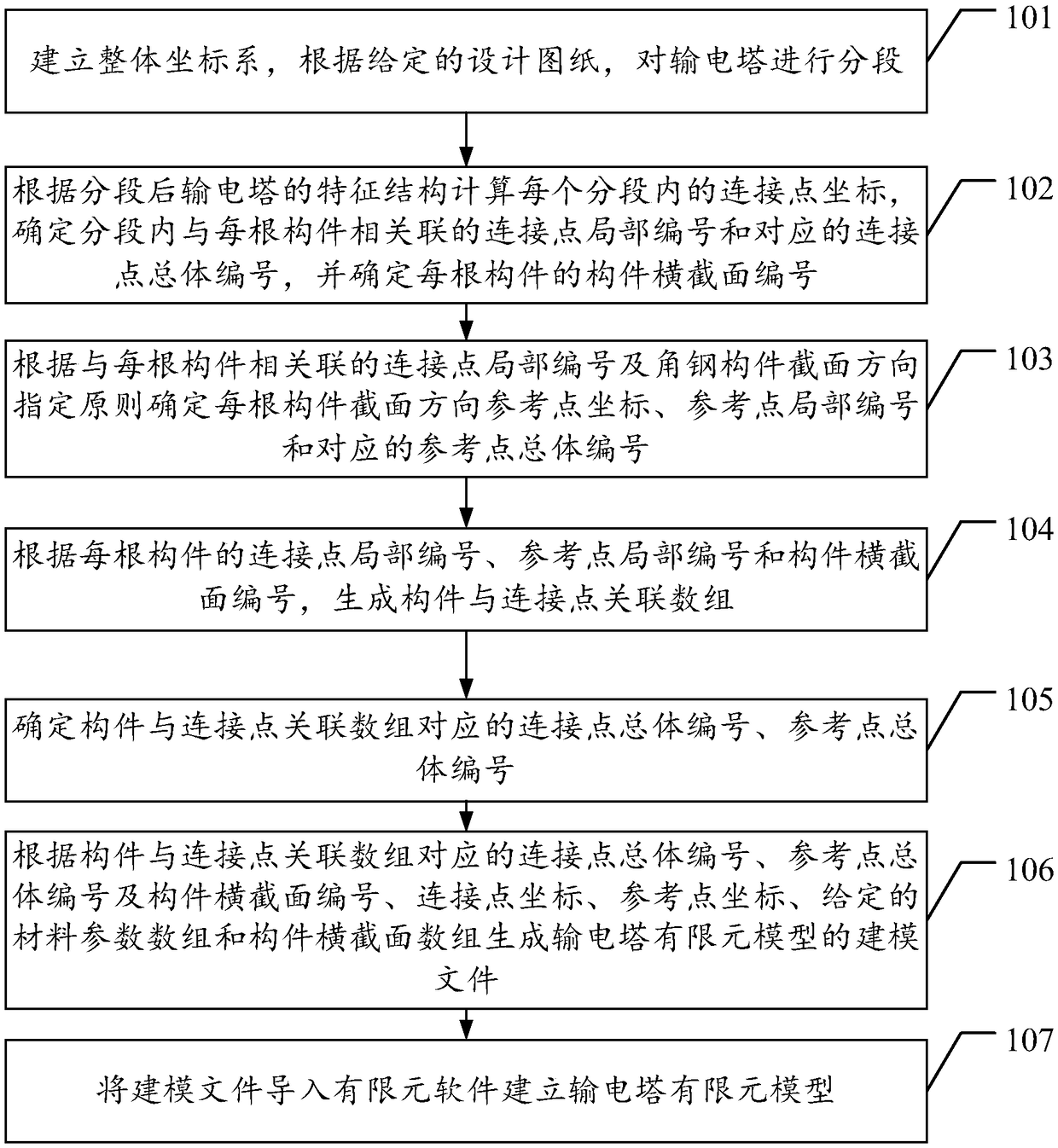
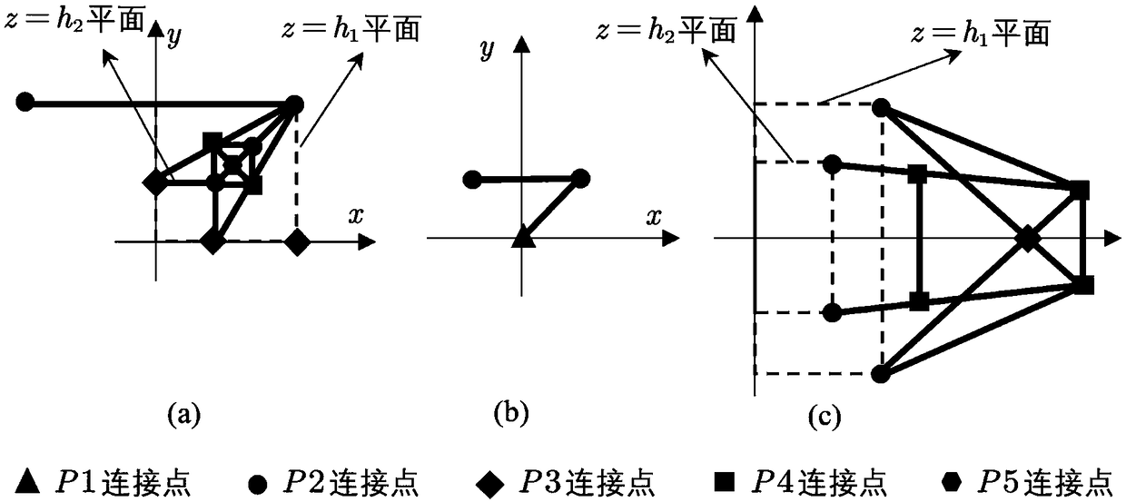
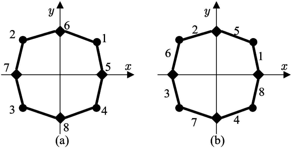
The invention performs the following steps: segmenting a power transmission tower, determining the local serial number of a connection point associated with each component and the serial number of thecomponent cross section in each segment in a segment-by-segment mode, determining the local serial number of a reference point according to the connection point and an angle steel component sectionaldirection designation principle, further generating an associative array of the component and the connection point, generating a modeling file of a finite element model of the power transmission tower, and establishing the finite element model of the power transmission tower. Since the modeling file of the invention includes the overall serial number of the connection point, the overall serial number of the reference point, the serial number of the component cross section, a connection point coordinate and a reference point coordinate, the direction of the cross section of an angle steel component can be quickly and correctly determined according to the reference point, the model can be ensured to be closer to a prototype, and the technical problem that a traditional modeling technique cannot quickly and correctly determine the direction of the cross section of the angle steel component can be solved.

Description

technical field [0001] The invention relates to the technical field of establishing a transmission tower model, in particular to a method and device for establishing a finite element model of an electric transmission tower. Background technique [0002] With the rapid development of my country's economy, the demand for electric energy continues to increase. my country has a vast territory and the construction of power grids is developing rapidly. Due to the influence of topography, climate characteristics, and human environment, the transmission towers are designed in various types and shapes. different. [0003] In order to better evaluate the safety of the transmission tower and the tower line system under the action of environmental loads, it is necessary to establish an analysis model of the transmission tower, the most commonly used is the finite element model. Due to the wide variety of transmission towers, especially the complex spatial distribution of the angle steel...

Claims


Application Information

Patent Timeline
Patent Type & Authority Applications(China)
IPC IPC(8): G06F17/50
CPCG06F30/23
Inventor 黄正刘石杨毅高庆水张楚聂铭
Owner ELECTRIC POWER RES INST OF GUANGDONG POWER GRID
Learn More