
Novel multifunctional power electrical transformer

A power electrical and multi-functional technology, applied in the direction of transformer/inductor shell, transformer/inductor cooling, transformer/inductor components, etc., can solve problems such as single function, low safety performance, and inability to meet the needs of use, to achieve High safety performance, powerful function, good lightning protection effect

Inactive Publication Date: 2018-11-06
肇庆中能创智信息科技有限公司
View PDF6 Cites 11 Cited by
  • Summary
  • Abstract
  • Description
  • Claims
  • Application Information

AI Technical Summary

Problems solved by technology

[0003] After searching, the Chinese patent application number is 201710847790.0, which discloses a power transformer, including a transformer shell, a transformer base at the bottom of the transformer shell, a ceramic bushing installed on the upper part of the transformer shell, a magnetic core and a magnetic core wound on the transformer shell. Three sets of winding coils, with insulating coating on the winding coils, the power transformer in the above patent has a simple design structure, a single function, and low safety performance, which obviously cannot meet the needs of people.

Method used

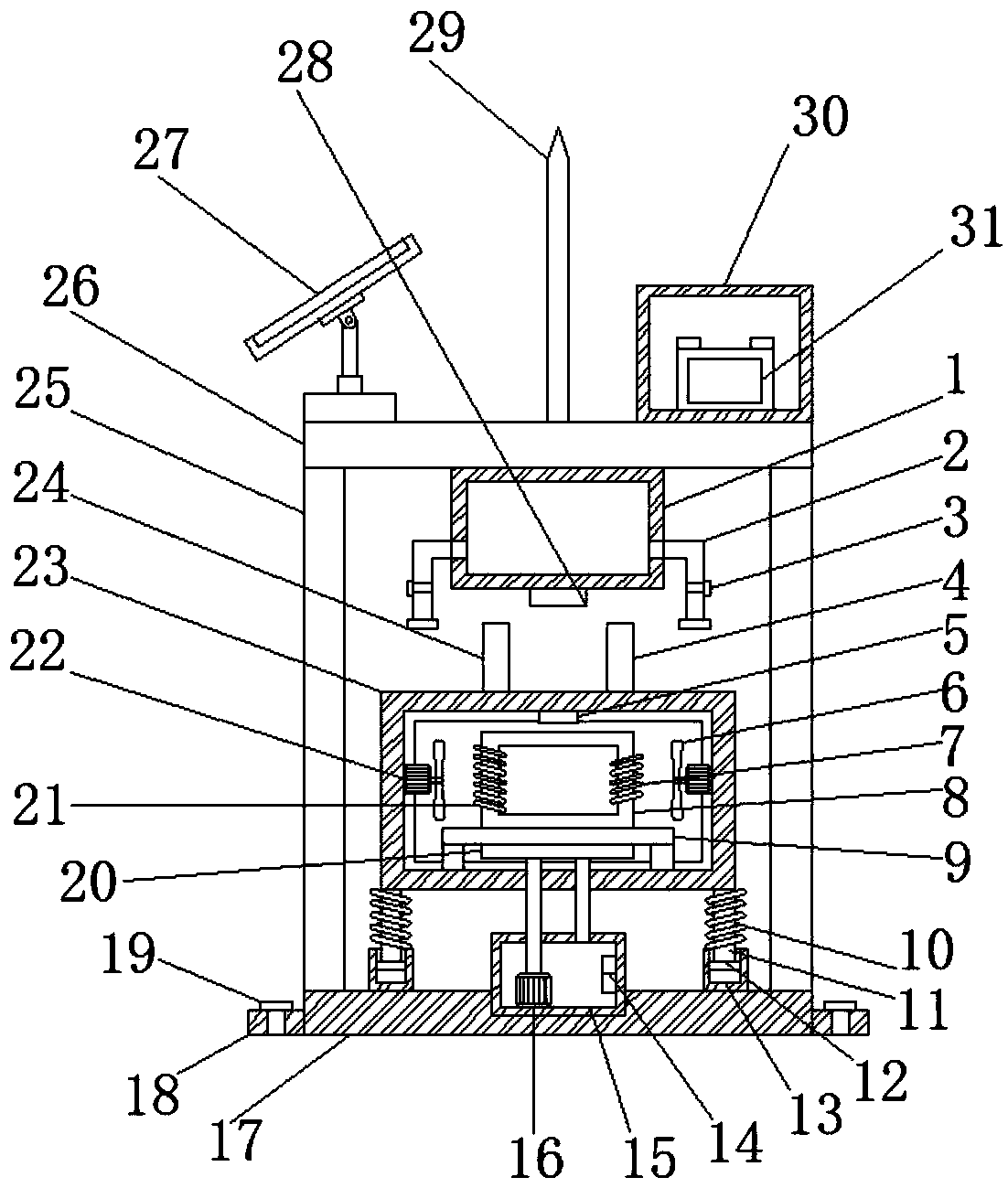

Image

  • Novel multifunctional power electrical transformer
  • Novel multifunctional power electrical transformer
  • Novel multifunctional power electrical transformer

Examples


Embodiment Construction

[0025] The following will clearly and completely describe the technical solutions in the embodiments of the present invention with reference to the accompanying drawings in the embodiments of the present invention. Obviously, the described embodiments are only some, not all, embodiments of the present invention.

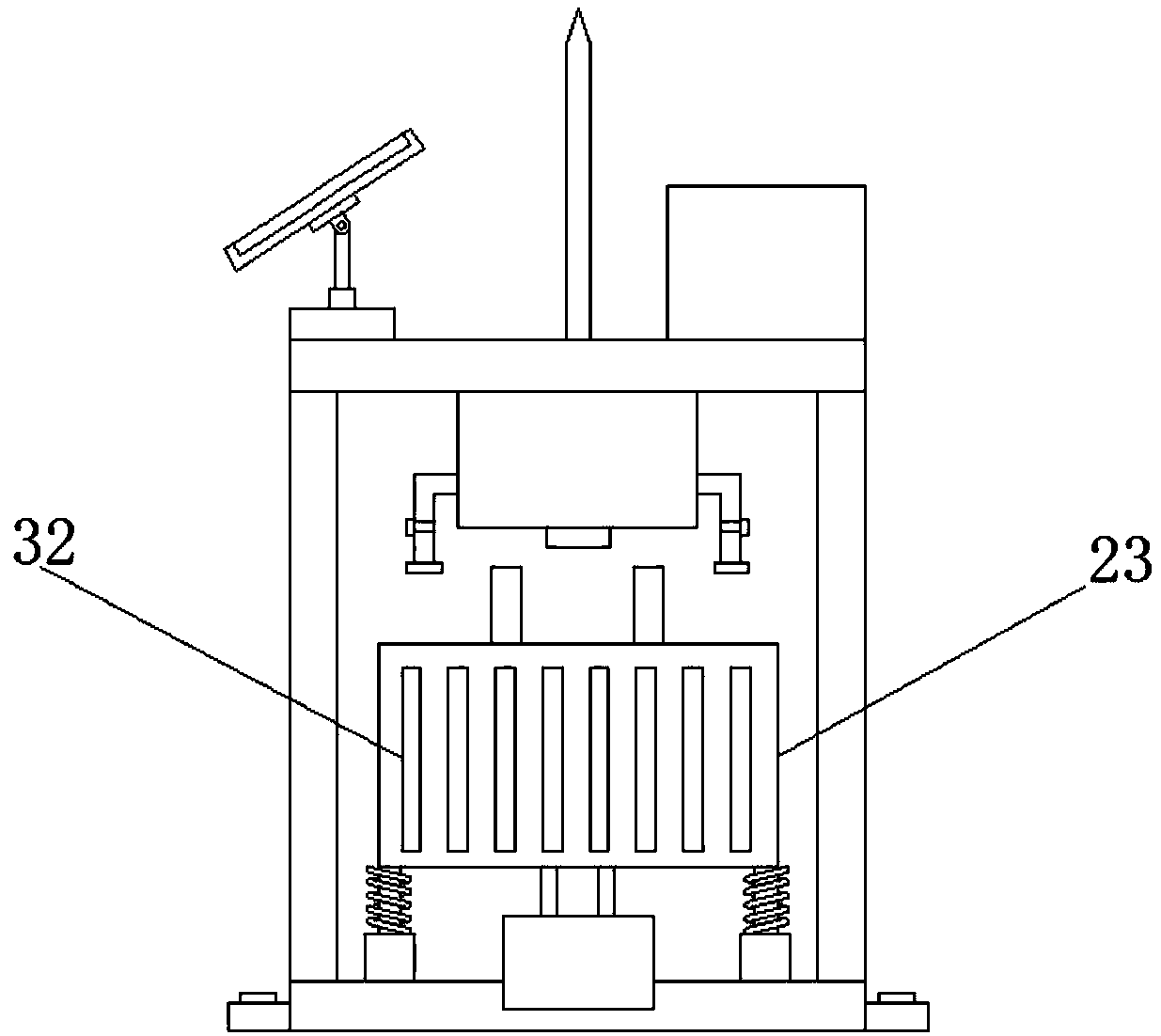
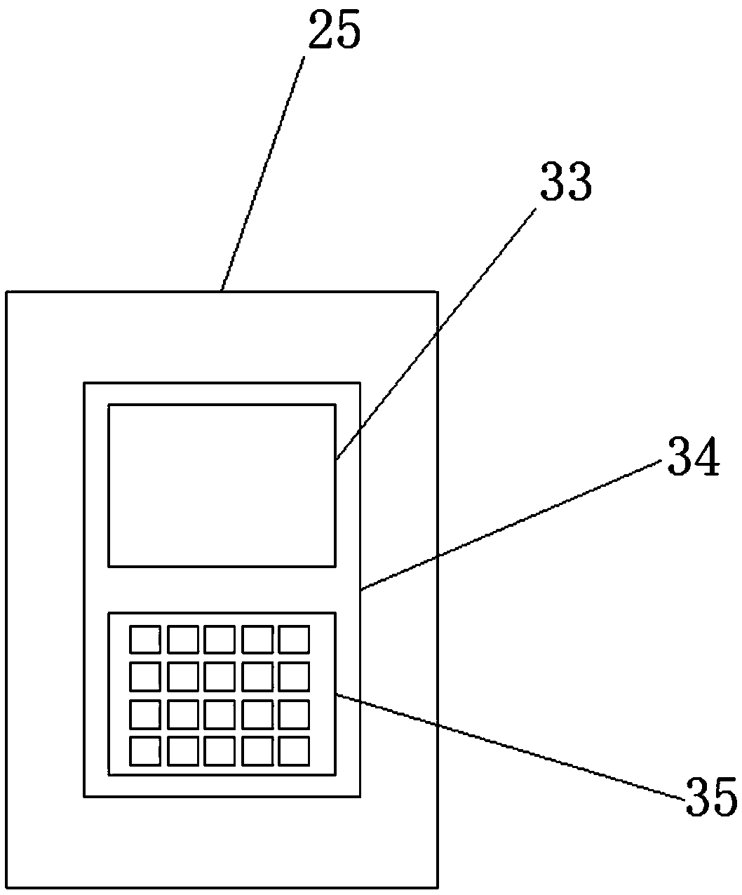
[0026] refer to Figure 1-5 , a new type of multifunctional electric power transformer, including a base 17, the four corners of the top outer wall of the base 17 are welded with a sleeve 13, and the inner wall of the sleeve 13 is slidably connected with a piston 12, and the top outer wall of the piston 12 is welded with a support rod 11 , and the outer wall of the support rod 11 is sleeved with a shock absorbing spring 10, the top outer wall of the support rod 11 is fixed with a housing 23 by screws, and the bottom inner wall of the housing 23 is fixed with a mounting platform 9 by screws, and the bottom outer wall of the mounting platform 9 The heat dissipation pla...


PUM


Abstract

The invention belongs to the technical field of power equipment, and especially relates to a novel multifunctional power electrical transformer in order to solve the problems of simple design structure, single function, and low safety performance of a power transformer. The novel multifunctional power electrical transformer comprises a base, wherein four corners of an outer wall of the top of thebase are all welded with sleeves, and an inner wall of the each sleeve is slidingly connected with a piston, an outer wall of the top of the piston is welded with a supporting rod, a damping spring sleeves an outer wall of the supporting rod, a shell is fixed to an outer wall of the top of the supporting rod through a screw, a mounting platform is fixed to an inner wall of the bottom of the shellthrough a screw, and a heat dissipation plate is fixed to an outer wall of the bottom of the mounting platform through a screw. The novel multifunctional power electrical transformer of the inventionhas the beneficial effects of good heat dissipation effect, capacity for preventing burnout of components inside the shell caused by excessively high temperature inside the shell, capacity for significantly prolonging a service life of the transformer, high intelligence degree, capacity for reducing property loss caused by firing of the transformer, high safety performance, and powerful functions.

Description

technical field [0001] The invention relates to the technical field of power equipment, in particular to a novel multifunctional electric power transformer. Background technique [0002] Transformer is a device that uses the principle of electromagnetic induction to change AC voltage. The main components are primary coil, secondary coil and iron core. The main functions are: voltage conversion, current conversion, impedance conversion, isolation, voltage stabilization, etc., which can be divided according to the purpose For: power transformers and special transformers, circuit symbols often use T as the beginning of the number. Example: T01, T201, etc. The principle of transformer transformation was first discovered by Faraday, but it was not practically applied until the 1880s. In the competition that the power plant should output direct current and alternating current, it is one of its advantages that the alternating current can use a transformer, which can convert the ele...

Claims


Application Information

Patent Timeline
IPC IPC(8): H01F27/08H01F27/16H01F27/22H01F27/40H01F27/02H01F27/06A62C3/16A62C35/13
CPCA62C3/16A62C35/13H01F27/025H01F27/06H01F27/085H01F27/16H01F27/22H01F27/40H01F27/402H01F2027/406
Inventor 陆云锋
Owner 肇庆中能创智信息科技有限公司
Learn More