
Laser galvanometer coil and winding process thereof

A laser vibrating mirror and coil technology, which is applied in coil manufacturing, inductance/transformer/magnet manufacturing, electrical components, etc., can solve the problems of complex manufacturing process, cumbersome manufacturing process, and low production efficiency

Inactive Publication Date: 2018-11-06
东莞市台立电子机械有限公司
View PDF0 Cites 1 Cited by
  • Summary
  • Abstract
  • Description
  • Claims
  • Application Information

AI Technical Summary

Problems solved by technology

[0003] The technical problem to be solved by the present invention is to provide a laser vibrating mirror coil and its winding process, which can be formed in the process of winding the coil, which realizes the difference between the wound coil and the formed coil. The process is integrated into one process, which simplifies the production process, improves production efficiency and production capacity, and makes the production of coils more convenient, and the coils wound by it have the advantages of good forming effect, high winding precision and high yield rate. , which makes the winding of the coil more simple, convenient and fast, and solves the problem that the current laser galvanometer coil and its winding process need to be wound into a parallel coil by a parallel winding machine, and then it needs to be pressed and formed by a mold , this mode of operation leads to problems such as complex production process, cumbersome production process, low production efficiency and low pass rate of finished products.

Method used


Image

  • Laser galvanometer coil and winding process thereof

Examples


Embodiment Construction

[0020] In order to facilitate the understanding of the present invention, the present invention will be described more fully below with reference to the associated drawings. Preferred embodiments of the invention are shown in the accompanying drawings. However, the present invention can be embodied in many different forms and is not limited to the embodiments described herein. On the contrary, the purpose of providing these embodiments is to make the disclosure of the present invention more thorough and comprehensive.

[0021] Unless otherwise defined, all technical and scientific terms used herein have the same meaning as commonly understood by one of ordinary skill in the technical field of the invention.

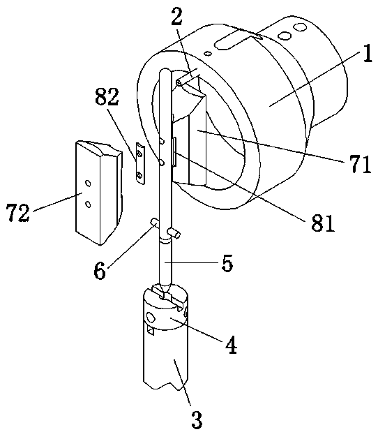
[0022] In this example, refer to figure 1 As shown, the present invention is a laser vibrating mirror coil, comprising a flying fork bowl 1, a wire needle 2 is arranged on the edge of the front side of the flying fork bowl 1, and a rotating pole shaft 3 is arranged on o...


PUM


Abstract

The invention relates to a laser galvanometer coil and a winding process thereof. The laser galvanometer coil comprises a fork bowl, a wire needle, a rotating polar shaft, a spindle base, a spindle, alocating pin, a first wire block, a second wire block, a first mould core, a second mould core, a limiting groove, a spindle mounting hole and a rotary servo motor. According to the laser galvanometer coil provided by the invention, the coil can be molded in the process of winding the coil, thus the production process is simplified, the production efficiency and the productivity are improved, andthe coil is more convenient to manufacture; and the wound coil has the advantages of being good in molding effect, high in winding precision and high in yield, the winding of the coil is simpler, more convenient and faster, and the problems that the existing laser galvanometer coil and the winding process thereof need to be wound into a parallel coil by adopting a parallel winding machine, and then need to be pressed and formed by a mold, which results in complicated manufacturing process and complicated manufacturing process, low production efficiency and low qualification rate of finished products are solved.

Description

technical field [0001] The invention relates to a laser vibrating mirror coil and its winding process. Background technique [0002] The current laser galvanometer coil is first wound into a parallel coil by a parallel winding machine, and then the parallel coil is removed. Then, the removed parallel coil is pressed and formed through a mold. This winding process has a complicated manufacturing process. , The production process is loaded down with trivial details, production efficiency is low and the qualified rate of finished product is low etc., and it does not meet the requirement of large-scale mass production and high-precision production of enterprises. Contents of the invention [0003] The technical problem to be solved by the present invention is to provide a laser vibrating mirror coil and its winding process, which can be formed in the process of winding the coil, which realizes the difference between the wound coil and the formed coil. The process is integrate...

Claims


Application Information

Patent Timeline
Patent Type & Authority Applications(China)
IPC IPC(8): H01F41/09H01F41/082H01F41/071
CPCH01F41/09H01F41/071H01F41/082
Inventor 郭燕军刘耀伟
Owner 东莞市台立电子机械有限公司
Learn More