A truss-supported flexible rib parabolic cylinder deployable antenna device

A parabolic cylinder and antenna device technology, applied in the direction of antennas, electrical components, etc., can solve the problems that the vehicle cannot meet the launch requirements, the precision of the profile is difficult to meet the requirements, and the weight of the parabolic cylinder antenna is heavy, so that it is not easy to expand and the overall Weight reduction, light weight effect

Active Publication Date: 2020-11-20
XIDIAN UNIV +1
View PDF7 Cites 0 Cited by
  • Summary
  • Abstract
  • Description
  • Claims
  • Application Information

AI Technical Summary

Problems solved by technology

[0004] (1) The traditional parabolic antenna is composed of a supporting member supporting a metal parabolic reflective surface. The antenna is large in size and heavy in weight, and the vehicle cannot meet the launch requirements.
[0005] (2) The deployable parabolic antenna is either a deployable solid surface or inflatable. The deployable solid surface parabolic antenna uses a shape memory material as the deployment drive; the inflatable parabolic antenna adopts air inflation to realize the deployment of the antenna , the storage volume of the two antennas is significantly reduced, but the weight of the parabolic cylinder antenna on the solid surface is generally large, and the accuracy of the air-filled parabolic cylinder antenna cannot meet the requirements after deployment, and the stability is poor

Method used


Image

  • A truss-supported flexible rib parabolic cylinder deployable antenna device
  • A truss-supported flexible rib parabolic cylinder deployable antenna device
  • A truss-supported flexible rib parabolic cylinder deployable antenna device

Examples


Embodiment Construction

[0041] In order to make the object, technical solution and advantages of the present invention more clear, the present invention will be further described in detail below in conjunction with the examples. It should be understood that the specific embodiments described here are only used to explain the present invention, not to limit the present invention.

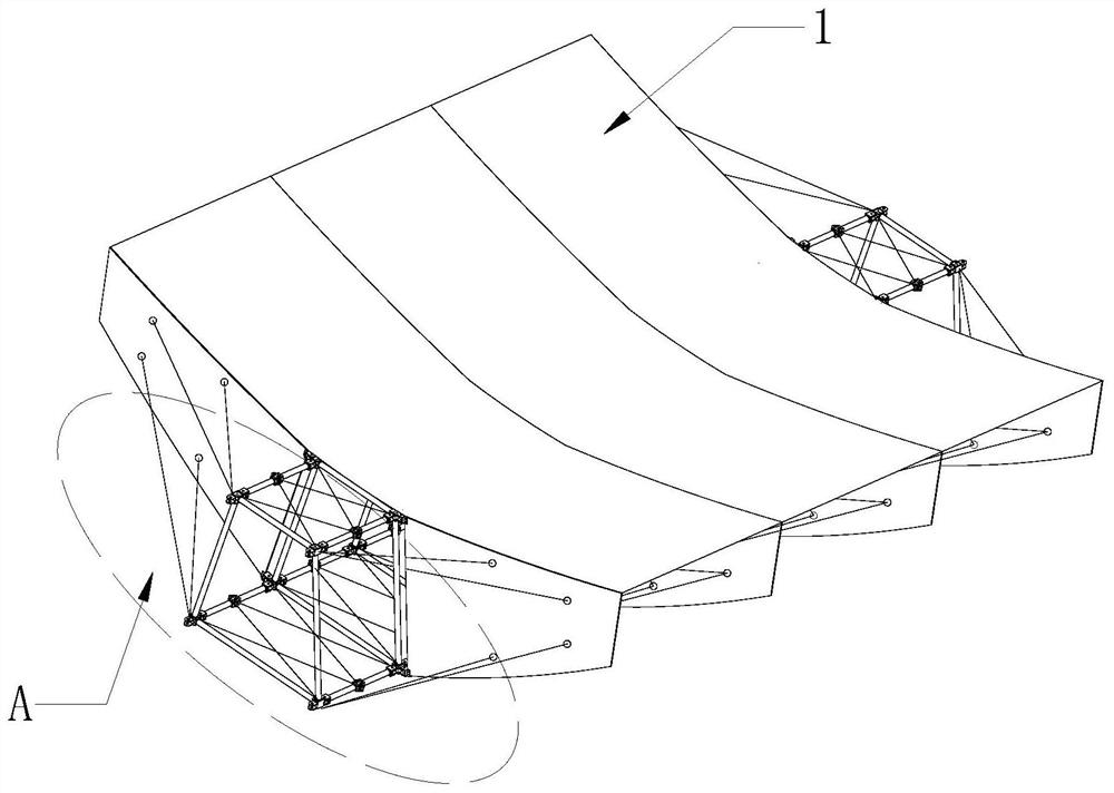
[0042] The present invention combines the truss expandable mechanism with the rib support structure in the parabolic cylinder deployable antenna, and proposes a structurally stable truss-supported flexible rib parabolic cylinder deployable antenna device, which has important practical significance.

[0043] Such as Figure 1-Figure 3 As shown, the truss-supported flexible rib parabolic cylinder deployable antenna device provided by the embodiment of the present invention is composed of a deployable support device A supporting a reflective film surface 1 . The deployable support device A includes a one-dimensional deployabl...


PUM


Abstract

The invention belongs to the satellite communication equipment technical field and discloses a truss supported flexible rib parabolic cylindrical unfoldable antenna device. An unfoldable supporting device A supports reflection film surfaces, so that the device can be formed; the unfoldable supporting device A comprises a one-dimensional unfoldable truss, unfolding control cables, rib plates and rib plate adjustment cables; the rib plates are symmetrically hinged to the left side edge and right side edge of the one-dimensional unfoldable truss respectively; the reflection film surfaces are attached onto the upper parabolic edges of the rib plates so as to form a parabolic cylindrical surface; the unfolding control cables are arranged at the upper surface and the lower bottom surface of theone-dimensional unfoldable truss so as to control the unfolding of the one-dimensional unfoldable truss; and the rib plate adjustment cables are arranged at two sides of each rib plate and are used for adjusting the unfolding positions and overall stiffness of the rib plates. According to the truss supported flexible rib parabolic cylindrical unfoldable antenna device of the invention, the one-dimensional truss mechanism is combined with the flexible rib structures, the truss mechanism can be folded and unfolded; the rib plates can be folded through winding, and unfolded flexibly; and after being folded, the device just occupies a small space, and therefore, a storage space for the device is obviously reduced, and the overall weight of the device is significantly reduced.

Description

technical field [0001] The invention belongs to the technical field of satellite communication equipment, and in particular relates to a truss-supported flexible rib parabolic cylinder expandable antenna device. Background technique [0002] At present, the existing technologies commonly used in the industry are as follows: At present, satellite systems play a pivotal role in the fields of deep space exploration, radar communication, and military engineering. As the "eyes" and "ears" of satellite systems, satellite-borne antennas play an important role in various tasks and are indispensable. One of the few key devices. With the continuous development of modern satellite technology, higher and higher requirements are put forward for the high frequency band, high gain and large aperture of the antenna. Due to the limitation of space and launch cost of existing rocket fairings, spaceborne antennas are required to be light in weight and small in size. Therefore, large-diameter...

Claims


Application Information

Patent Timeline
Patent Type & Authority Patents(China)
IPC IPC(8): H01Q15/16
CPCH01Q15/161
Inventor 杜敬利孙国辉陈晓峰周鑫保宏张逸群杨东武
Owner XIDIAN UNIV
Why Eureka
Try Eureka