Flat-surface milling machine

A technology of plane milling machine and milling head, which is applied in the direction of processing machines for manufacturing flat surfaces, rotary cutting tools, fine planers, etc. It can solve the problems of poor surface quality and the inability to achieve the efficiency of plane milling machines, etc., and achieve installation/adjustment or The effect of simple tool change

Inactive Publication Date: 2002-07-17
ROBERT BOSCH GMBH
View PDF1 Cites 0 Cited by
  • Summary
  • Abstract
  • Description
  • Claims
  • Application Information

AI Technical Summary

Problems solved by technology

Rather, the known machine is a face milling machine with conventional cutting edge geometry, which cannot achieve the efficiency of a face milling machine
[0004] The known stationary surface milling machines result in a poor surface quality when planing the end-faced wood and when the planing teeth emerge from the workpiece, since relatively coarse edge cracks occur here

Method used


Image

  • Flat-surface milling machine
  • Flat-surface milling machine
  • Flat-surface milling machine

Examples


Embodiment Construction

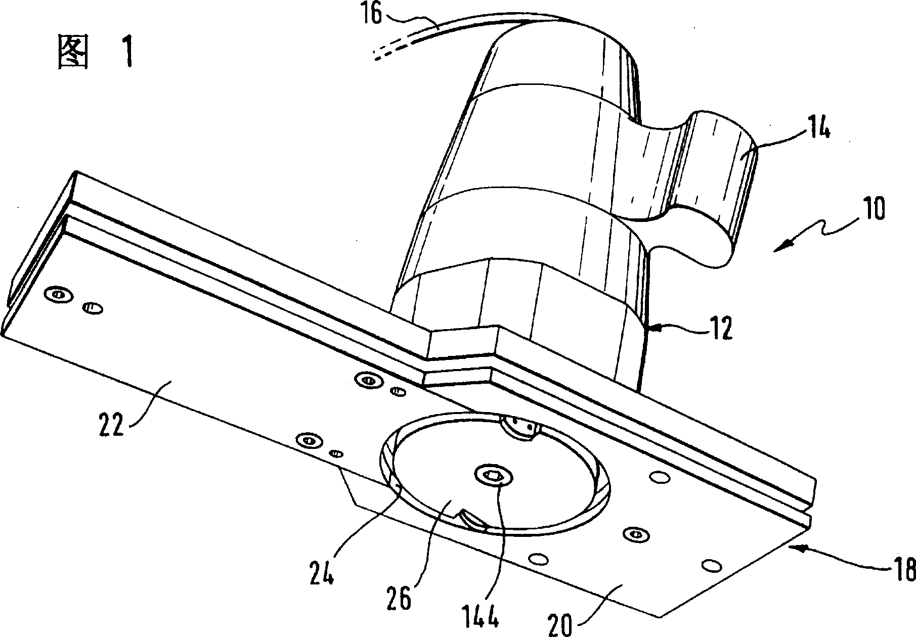
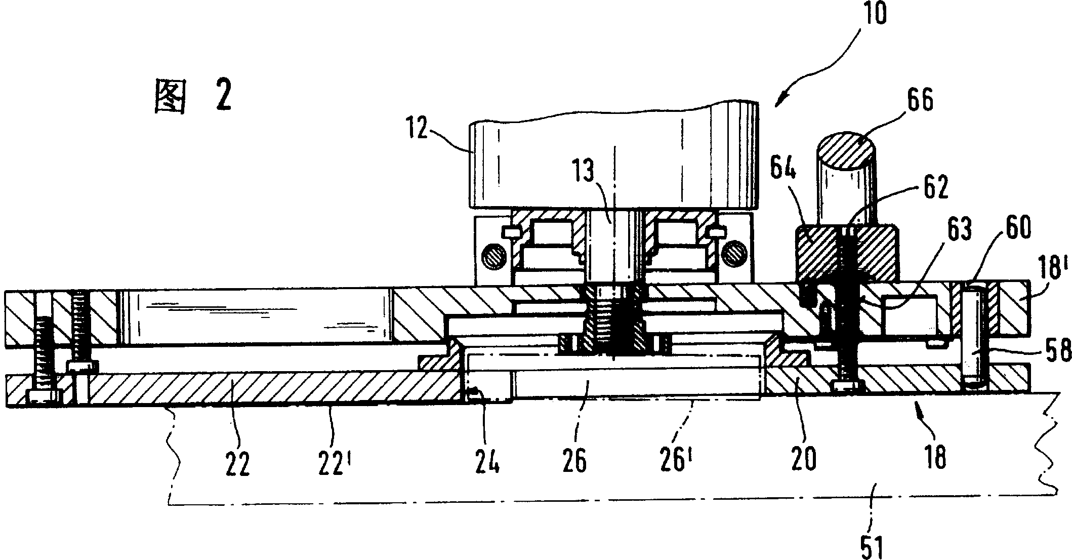
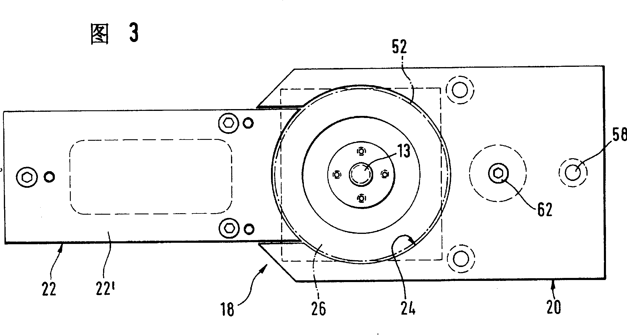
[0029] The plane milling machine ( 10 ) shown in perspective in FIG. 1 has an approximately cylindrical housing 12 extending axially from top to bottom in the viewing direction. The housing has a power supply cable 16 emerging from above and two handles 14 projecting radially laterally, only one of which is shown here, for operating the surface milling machine 10 on a workpiece not shown.

[0030] The lower part of the housing 12 is connected to a base plate 18 for being supported on a workpiece, which base plate consists of a front, axially adjustable, wide part 20 and a rear, fixed narrow part 22 . The base plate 18 is provided in the axial extension of the housing 12 with a circular through-opening 24 for passing through a disk-shaped milling head 26 for cutting into a workpiece (not shown). The through hole 24 is placed between the parts 20, 22 of the base plate 18, wherein a relatively small part of this hole 24 - viewed to the left - is formed by the narrow, fixed edge o...


PUM


Abstract

The present invention relates to a machine (10) for milling flat surfaces and for woodworking, wherein said machine comprises a drive motor which is connected to a working shaft (13) having at one free end a milling head (26) provided with milling edges (48, 50) on its front face (28). The milling head (26) is made in the form of a preferably disc-shaped body which is parallel to the surface of the work. The milling edges are supported by a preferably flat blade (38, 40) which is removably mounted on the milling head and comprises a main edge as well as a secondary edge. The purpose of this invention is to provide a particularly efficient flat-surface milling machine in the shape of a hand-held machine-tool. This machine (10) is reduced in weight and size and includes a housing (12) with a handle (14). The milling head (26) includes a blade (38) which has no main edge (50) and is provided with a secondary edge (48) only.

Description

technical field [0001] The invention relates to a plane milling machine. Background technique [0002] On page 762 of the specialist magazine HK6 / 94, a multi-blade sawing machine K34G / 1200 is mentioned, which is equipped with a special cutting milling cutter, which can saw and plan wood at the same time. This cutting mill has two types of teeth, broaching teeth and planing teeth. Only the main cutting edge is used for the actual cutting work by the broach teeth, which are arranged radially on the outermost circumference of the cut-off milling cutter. Every two broaching teeth are followed by a planing tooth, which reworks the previously broached, sawn somewhat rough cutting surface with an axial cutting edge. The cutting surface of the sawn part is smooth in some ways, however the smallest but clearly visible ring-shaped indentations occur due to the method, so that further processing, such as e.g. in painting or dipping, cannot be dispensed with in all cases Planing to b...

Claims


Application Information

Patent Timeline
Patent Type & Authority Patents(China)
IPC IPC(8): B27C1/02B27C1/00B27G13/12
CPCB27C1/005Y10T409/306608B27C1/00
Inventor 约尔格·德厄得马克西米利安·奥伯弗里德·肖尔茨
Owner ROBERT BOSCH GMBH
Why Eureka
Try Eureka