A detection method for the position of the leakage point of the underground concrete diaphragm wall

A detection method and technology of leakage point, which can solve the problem of incomplete detection of the leakage point position of the continuous wall by detecting the appearance of fluid at the leakage point, protection device, buoy liquid level indicator, etc., and achieve improved sealing performance, ensure comprehensiveness, and improve accuracy

Active Publication Date: 2021-12-24
JIANGSU TESTING CENT FOR QUALITY OF CONSTR ENG
View PDF9 Cites 0 Cited by
  • Summary
  • Abstract
  • Description
  • Claims
  • Application Information

AI Technical Summary

Problems solved by technology

[0005] In order to improve the problem of incomplete detection of the leakage point position of the diaphragm wall, this application provides a detection method for the leakage point position of the underground concrete diaphragm wall

Method used


Image

  • A detection method for the position of the leakage point of the underground concrete diaphragm wall
  • A detection method for the position of the leakage point of the underground concrete diaphragm wall
  • A detection method for the position of the leakage point of the underground concrete diaphragm wall

Examples


Embodiment Construction

[0044] Contraction below Figure 1-4 Further detailed description of the present application.

[0045] The present application discloses a method of detecting a leakage point position of an underground concrete continuous wall.

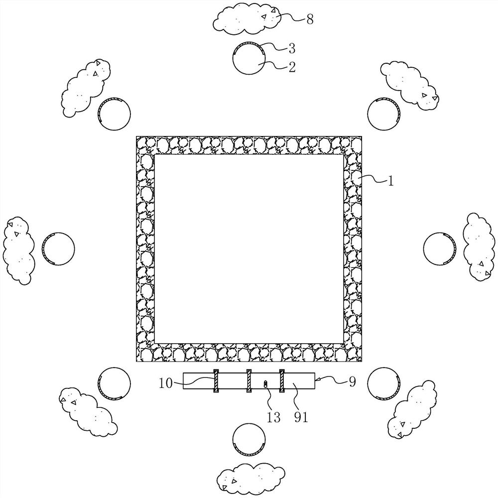
[0046] Refer figure 1 , A method of detecting the position of the underground concrete continuous wall leakage point, including the following steps:

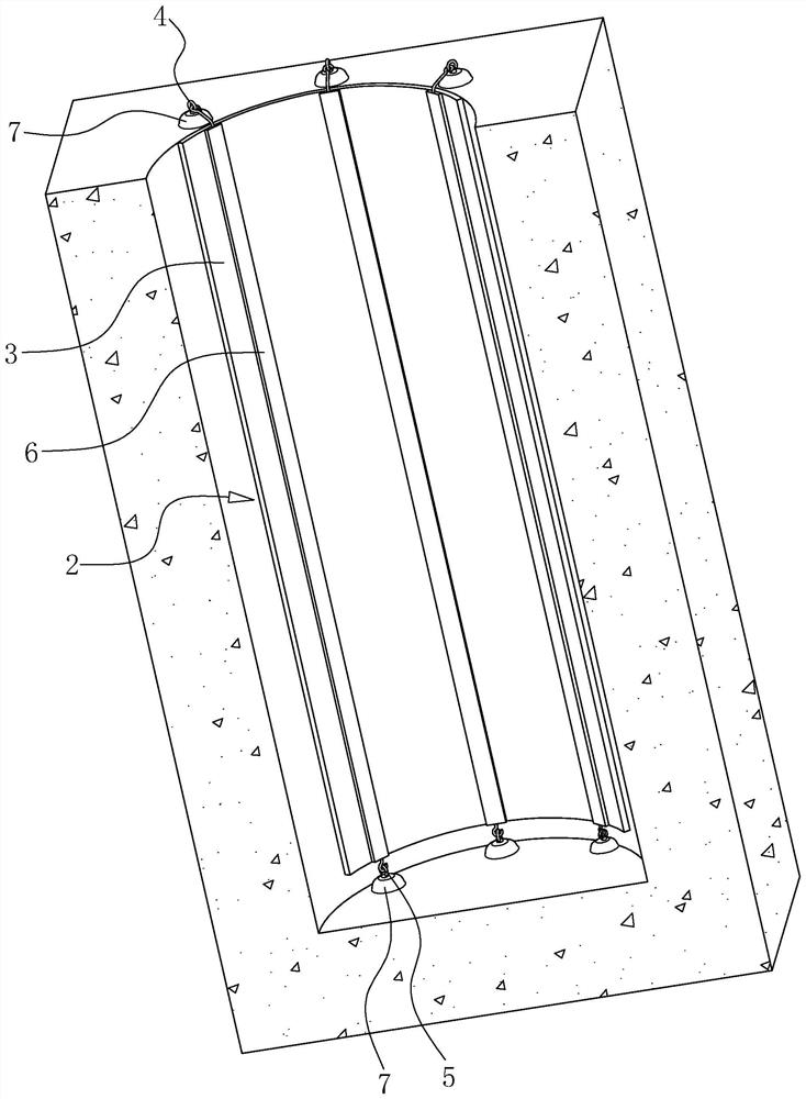
[0047] Step S1: Some primary consequences 2 were excavated at the outer circumference of the continuous wall 1, and then lay a layer of waterproof coil 3 on the inner wall of these initial convelation 2 on the side of the continuous wall 1, and then in the initial exploration 2 The peripheral injection of polyurethanes on the side of the continuous wall 1 is short-term sealing the water source, then drill the water in these initial conservations 2, and do the highest water level mark;

[0048] Step S2: Extract the underwater water in the region enclosed in the continuous wall 1;

[0049] Step S3: Observing t...


PUM


Abstract

This application relates to a detection method for the location of the leakage point of an underground concrete diaphragm wall, which includes S1: digging a preliminary survey well outside the diaphragm wall; S2: pumping groundwater inside the diaphragm wall; S3: observing the water level of the preliminary survey well to determine the drop of the water level The initial survey well corresponding to the diaphragm wall is the direction of the leakage point; S4: Dig a detection trench outside the leakage point area of ​​the diaphragm wall, and use a partition to divide the detection trench into multiple detection intervals; S5: Towards the detection trench Fill water and observe the water level of each detection interval. If the water level of a certain detection interval drops, determine the position of the leakage point corresponding to the continuous wall of the detection interval; S6: Pump out the water in the detection groove, take out the partition, and keep two partitions on both sides of the detection interval. Plate, backfill the rest of the detection area; S7: Irrigate the detection area step by step, and wait for a period of time after each irrigation, and observe the water level change. If the water level drops for a certain time, determine the position corresponding to the water level height as the final leak point position. The present application has the effect of improving the comprehensiveness of the position detection of the leakage point of the continuous wall.

Description

Technical field [0001] The present application relates to the field of continuous wall quality detection, in particular, involving a method of detecting a leakage point position of underground concrete continuous wall. Background technique [0002] The underground concrete continuous wall is referred to as the underground continuous wall or continuous wall, the continuous wall is the basic project uses a tank mechanical, along the peripheral axis of the deep excavation project, excavated a narrow deep deep groove. After the cleavage, the steel cage is placed in the groove, and the water concrete is fed with catheter method to build a cell slot. Since then, a continuous reinforced concrete wall is built underground, which is used as a cut, anti-seepage, load-bearing and water retaining structure. [0003] After the continuous wall is completed, in order to ensure the quality of the continuous wall, it is often necessary to prevent the continuous wall to prevent seepage detection. ...

Claims


Application Information

Patent Timeline
Patent Type & Authority Patents(China)
IPC IPC(8): G01M3/04G01F23/58E02D31/02E02D31/10
CPCG01M3/04G01F23/58E02D31/02E02D31/10
Inventor 崇金玲
Owner JIANGSU TESTING CENT FOR QUALITY OF CONSTR ENG
Why Eureka
Try Eureka