A power busway fixing device

A technology of fixed equipment and busway, applied in the installation of busbars, electrical components, cables, etc., can solve the problems of low work efficiency, high labor intensity, complicated operation, etc., and achieve the effect of improving efficiency and reducing labor intensity

Active Publication Date: 2020-05-08
STATE GRID SHANDONG ELECTRIC POWER CO YUCHENG POWER SUPPLY CO
View PDF5 Cites 0 Cited by
  • Summary
  • Abstract
  • Description
  • Claims
  • Application Information

AI Technical Summary

Problems solved by technology

[0003] In order to solve the above problems, the present invention provides a power busway fixing device, which can solve the existing L-shaped wooden busway installation process that requires manual fixing of the L-shaped busway with the help of clamping tools. There are differences in the length and center of gravity of the busway, and manual adjustment of the clamping tool is required. There are errors in manual adjustment, which cannot ensure the stability of the busway during the transportation process, and it is easy to cause the busway to slip and break during the transportation process, which cannot be guaranteed. The installation angle of the busway needs to be corrected manually, the operation is complicated, the labor intensity is high and the work efficiency is low. It can realize the function of mechanized fixing and clamping of the L-shaped busway without manual operation, which can ensure the installation of the L-shaped busway. The angle can prevent the L-shaped bus duct from slipping and breaking during lifting, and has the advantages of simple operation, low labor intensity and high work efficiency.

Method used


Image

  • A power busway fixing device
  • A power busway fixing device
  • A power busway fixing device

Examples


Embodiment Construction

[0019] In order to make it easy to understand the technical means, creative features, objectives and effects achieved by the present invention, the present invention will be further explained below in conjunction with specific drawings.

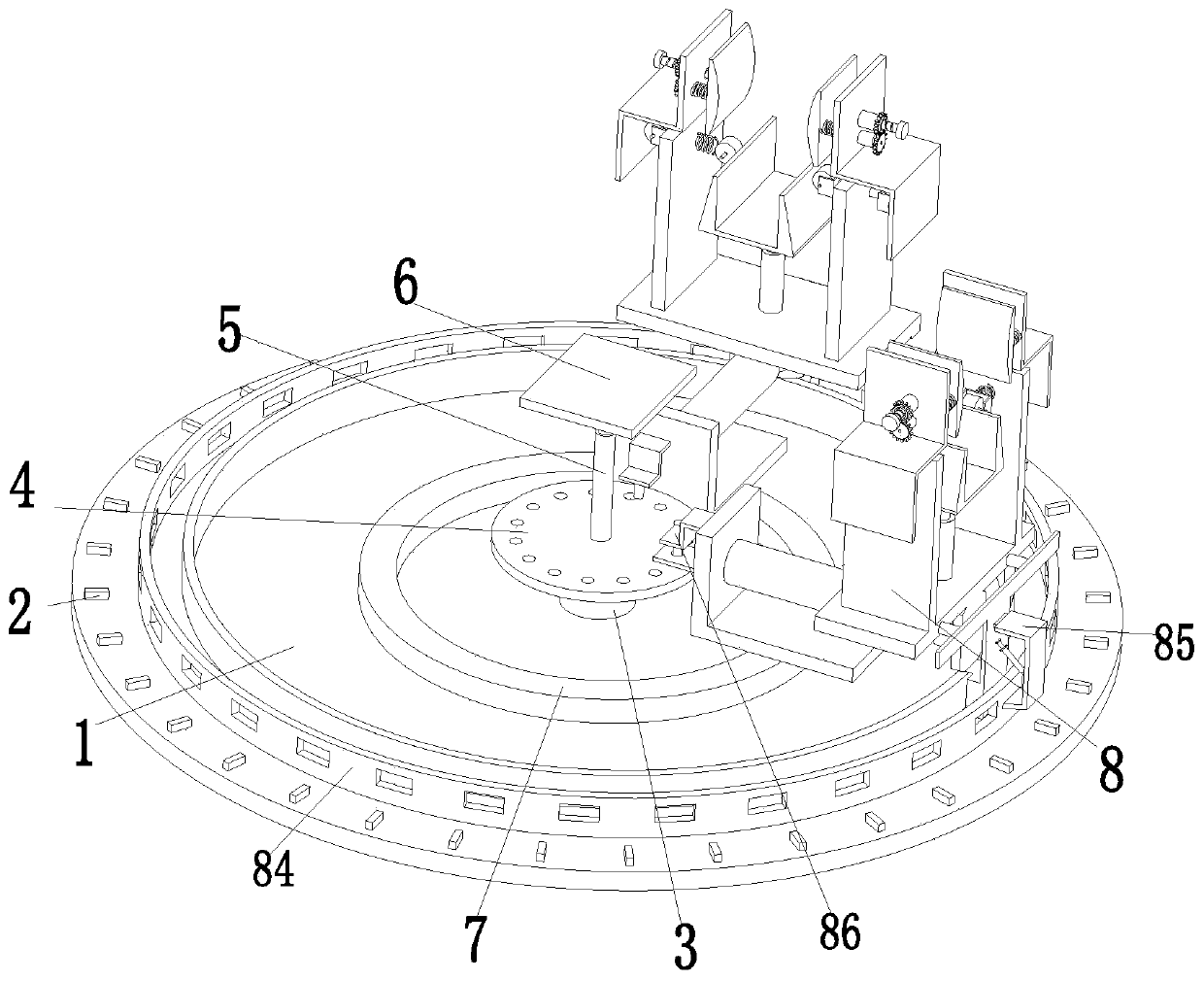
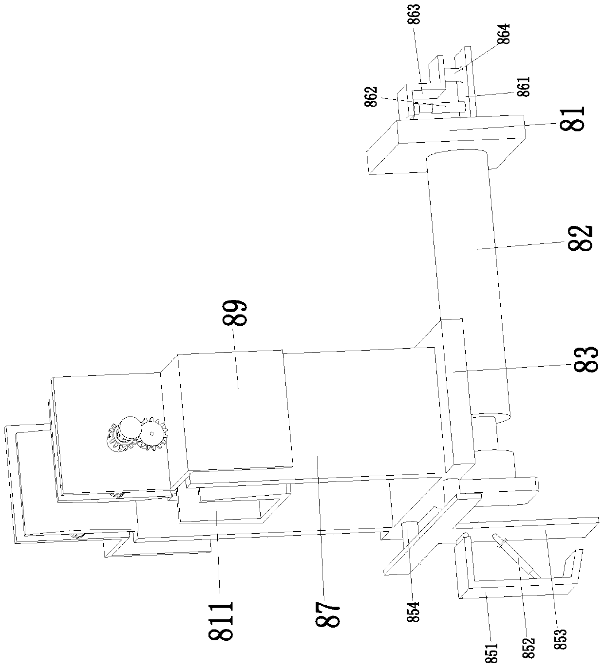
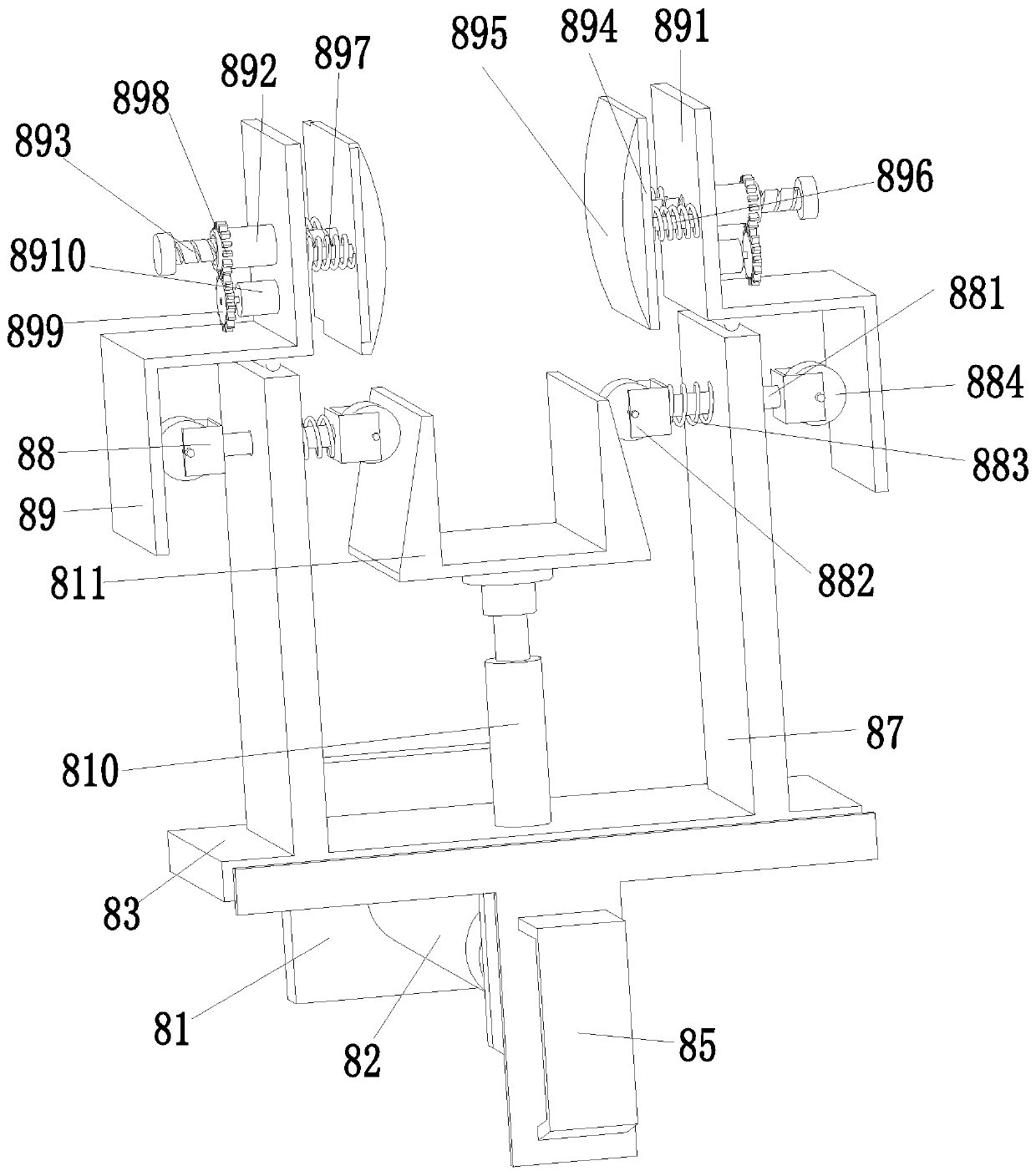
[0020] Such as Figure 1 to Figure 3 As shown, a power busway fixing device includes a bottom plate 1. A rotating support motor 3 is installed on the upper middle of the bottom plate 1 through a motor seat. A rotating support plate 4 is installed on the output shaft of the rotating support motor 3. A supporting lifting cylinder 5 is installed in the middle of the upper end. The top end of the supporting lifting cylinder 5 is mounted on the supporting lifting plate 6 through a flange. The rotating supporting plate 4 is evenly provided with limit adjustment holes along its circumferential direction. The bottom plate 1 is equipped with a ring The sliding block 7 has two adjusting and fixing devices 8 installed on the annular sliding block 7; the bo...


PUM


Abstract

An apparatus for fixing a power bus slot comprises a bottom plate, a rotary supporting motor is installed at the upper end and the middle part of the bottom plate through a motor seat, a rotary supporting plate is installed on the output shaft of the rotary supporting motor, a position limit adjusting holes are uniformly arranged in the rotary supporting plate along the circumferential direction thereof, an annular slider is installed on the bottom plate, and two adjusting fixing devices are installed on the annular slider. The invention can solve the problem that the L-shaped wooden bus slotin the prior L-shaped wooden bus slot installation process needs manual fixation of the L-shaped structure bus slot by means of a clamping tool, there are differences in center of gravity, bus slot lengths of different specifications, etc. The clamping tools need to be adjusted manually, and there are errors in the manual adjustment, which cannot ensure the stability of the bus slot in the conveying process, easily make the bus slot slip and break in the conveying process, cannot ensure the installation angle of the bus slot, need to be corrected manually, the operation is complex, the labor intensity is high and the work efficiency is low, and other problems also exist.

Description

Technical field [0001] The invention relates to the field of power equipment, in particular to a fixed equipment for power bus ducts. Background technique [0002] The bus duct is a closed metal device composed of copper and aluminum bus bars. The bus duct has a series of matching, commercial production, small size, large capacity, short design and construction period, convenient assembly and disassembly, no burning, safe and reliable , Long service life, etc., are widely used in the power supply system of high-rise buildings. The busway is the main power supply line in the electric shaft. According to the shape, the busway can be divided into X-type, Z-type and L-type. During the installation process of the busway, it is necessary to manually fix the busway of the L-shaped structure with a clamping tool. The length and center of gravity of the busway of different specifications are different, and the clamping tool needs to be adjusted manually. The manual adjustment has errors a...

Claims


Application Information

Patent Timeline
Patent Type & Authority Patents(China)
IPC IPC(8): H02G5/00
CPCH02G5/00
Inventor 徐格利许强高传华郑文豪
Owner STATE GRID SHANDONG ELECTRIC POWER CO YUCHENG POWER SUPPLY CO
Why Eureka
Try Eureka