Optical signal receiving device, method and coherent optical transmission system with the device

A technology for receiving devices and optical signals, applied in transmission systems, electromagnetic wave transmission systems, electromagnetic receivers, etc., can solve the problems of high cost of lasers, and achieve the effect of solving high costs and reducing system costs

Active Publication Date: 2018-11-06
WUHAN POST & TELECOMM RES INST CO LTD
View PDF4 Cites 14 Cited by
  • Summary
  • Abstract
  • Description
  • Claims
  • Application Information

AI Technical Summary

Problems solved by technology

[0005] In view of the defects in the prior art, the object of the present invention is to provide an optical signal receiving device, method and coherent optical transmission system with the device, which can solve the problem of high cost of lasers in the existing coherent optical transmission system

Method used


Image

  • Optical signal receiving device, method and coherent optical transmission system with the device
  • Optical signal receiving device, method and coherent optical transmission system with the device
  • Optical signal receiving device, method and coherent optical transmission system with the device

Examples


Embodiment 1

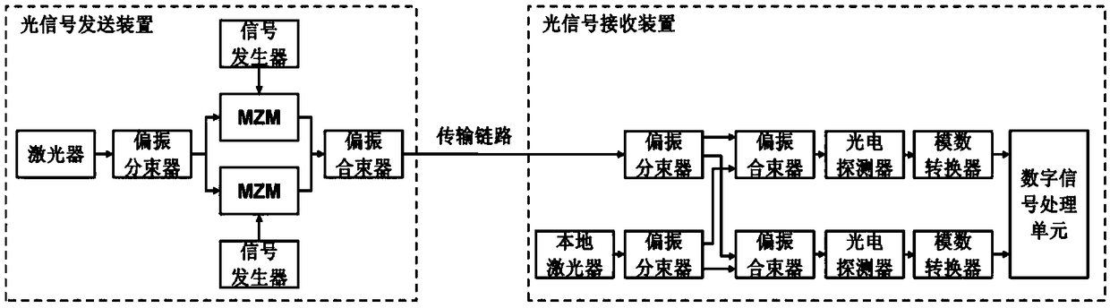
[0048] see figure 1 As shown, this embodiment provides an optical signal receiving device for demodulating carrier-suppressed dual-polarized optical signals, including:

[0049] a local laser for generating local oscillator light;

[0050] Two polarization beam splitters, one polarization beam splitter is used to split the received carrier-suppressed dual-polarized intensity-modulated optical signal into two independent polarized received optical signals, that is, the x-polarized received optical signal and the y-polarized received optical signal; Another polarization beam splitter is used to split the local oscillator light generated by the local laser into two independent polarized local oscillator lights, namely x-polarized local oscillator light and y-polarized local oscillator light;

[0051] Two polarization beam combiners, one polarization beam combiner is used to couple the x-polarized received optical signal and the x-polarized local oscillator light to obtain the x-...

Embodiment 2

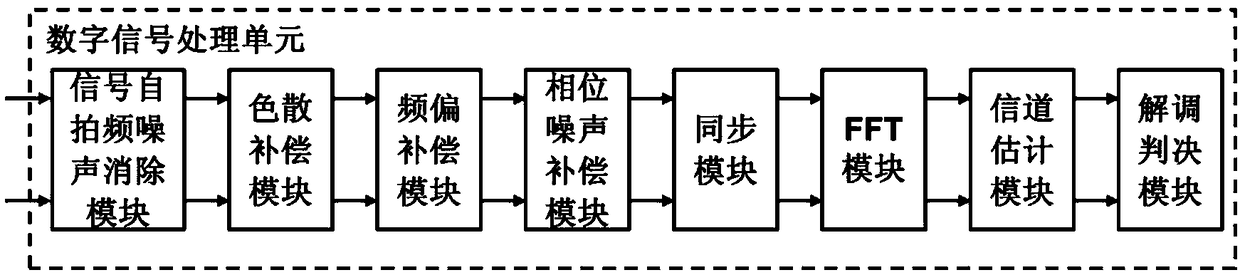
[0057] The basic structure of the optical signal receiving device provided in this embodiment is the same as that of Embodiment 1, the difference lies in that in the digital signal processing unit of the device, the Selfie frequency noise elimination module eliminates the interference caused by the Selfie frequency of the signal. The specific implementation process of the impact of system performance includes:

[0058] 1) Calculate the amplitude a of the x polarization recovery signal and the y polarization recovery signal x,y (n); the calculation formula is:

[0059]

[0060] where r x,y (n) represents the x-polarized received electrical signal and the y-polarized received electrical signal obtained after the analog-to-digital converter;

[0061] 2) Calculate the phase of x polarization recovery signal and y polarization recovery signal The calculation formula is:

[0062]

[0063] In the formula, sign(ω) represents the sign function, which is 1 when ω>0, 0 when ω=0...

Embodiment 3

[0067] The basic structure of an optical signal receiving device provided in this embodiment is the same as that of Embodiment 1, except that in the digital signal processing unit of the device, the phase noise compensation module uses a phase noise compensation algorithm to eliminate the phase of the signal The specific implementation process of noise includes:

[0068] 1) Use a digital low-pass filter to filter the x-polarized signal and y-polarized signal with phase noise respectively to obtain the suppressed carrier signal c x,y (n);

[0069] 2) Obtain the amplified carrier signal k c through digital amplification technology x,y (n), where k is an amplification factor;

[0070] 3) Calculate the dual polarization signal r_pnc without phase noise x,y (n); the calculation formula is:

[0071] r_pnc x,y (n)=|r_foc x,y (n)+k·c x,y (n)|-|k·c x,y (n) | Formula (4).


PUM


Abstract

The invention discloses an optical signal receiving device, an optical signal receiving method, and a coherent optical transmission system with the device, relating to the field of coherent optical transmission systems. The optical signal receiving device comprises: a local laser, two polarization beam splitters, two polarization beam combiners, two photodetectors, two analog to digital converters, and a digital signal processing unit, wherein the digital signal processing unit comprises a self-beating frequency noise eliminating module configured to eliminate the influence of the self-beatingfrequency of the signal on the system performance, and a phase noise compensation module configured to eliminate the phase noise of the signal by utilizing the phase noise compensation algorithm. Theinvention is capable of solving the problem of high cost of laser in the existing coherent optical transmission system.

Description

technical field [0001] The invention relates to the field of coherent optical transmission systems, in particular to an optical signal receiving device and method and a coherent optical transmission system with the device. Background technique [0002] Due to the continuous bandwidth increase in metropolitan area network transmission and the high-speed data interconnection between various data centers, the transmission capacity and transmission distance of the system are further improved in short- and medium-distance transmission. Therefore, coherent optical technology is applied to short- and medium-distance optical Transmission systems have been extensively studied. [0003] In the existing coherent optical transmission system, both the optical signal sending device and the optical signal receiving device need to have a laser, the laser in the optical signal sending device is used as the sending laser, and the local laser in the optical signal receiving device is used as t...

Claims


Application Information

Patent Timeline
Patent Type & Authority Applications(China)
IPC IPC(8): H04B10/61
CPCH04B10/614H04B10/616
Inventor 黎偲李响罗鸣
Owner WUHAN POST & TELECOMM RES INST CO LTD
Why Eureka
Try Eureka