Optical signal receiving device, method and coherent optical transmission system having the same
A technology for receiving devices and optical signals, applied in transmission systems, electromagnetic wave transmission systems, electromagnetic receivers, etc., can solve the problems of high cost of lasers, and achieve the effect of solving high costs and reducing system costs.
- Summary
- Abstract
- Description
- Claims
- Application Information
AI Technical Summary
Problems solved by technology
Method used
Image
Examples
Embodiment 1
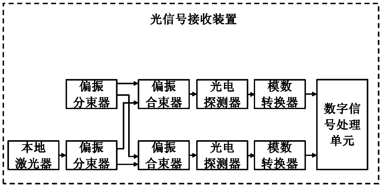
[0048] see figure 1 As shown, this embodiment provides an optical signal receiving device for demodulating carrier-suppressed dual-polarized optical signals, including:
[0049] a local laser for generating local oscillator light;
[0050] Two polarization beam splitters, one polarization beam splitter is used to split the received carrier-suppressed dual-polarized intensity-modulated optical signal into two independent polarized received optical signals, that is, the x-polarized received optical signal and the y-polarized received optical signal; Another polarization beam splitter is used to split the local oscillator light generated by the local laser into two independent polarized local oscillator lights, namely x-polarized local oscillator light and y-polarized local oscillator light;
[0051] Two polarization beam combiners, one polarization beam combiner is used to couple the x-polarized received optical signal and the x-polarized local oscillator light to obtain the x-...
Embodiment 2
[0057] The basic structure of the optical signal receiving device provided in this embodiment is the same as that of Embodiment 1, the difference lies in that in the digital signal processing unit of the device, the Selfie frequency noise elimination module eliminates the interference caused by the Selfie frequency of the signal. The specific implementation process of the impact of system performance includes:
[0058] 1) Calculate the amplitude a of the x polarization recovery signal and the y polarization recovery signal x,y (n); the calculation formula is:
[0059]
[0060] where r x,y (n) represents the x-polarized received electrical signal and the y-polarized received electrical signal obtained after the analog-to-digital converter;
[0061] 2) Calculate the phase of x polarization recovery signal and y polarization recovery signal The calculation formula is:
[0062]
[0063] In the formula, sign(ω) represents the sign function, which is 1 when ω>0, 0 when ω=0...
Embodiment 3
[0067] The basic structure of an optical signal receiving device provided in this embodiment is the same as that of Embodiment 1, except that in the digital signal processing unit of the device, the phase noise compensation module uses a phase noise compensation algorithm to eliminate the phase of the signal The specific implementation process of noise includes:
[0068] 1) Use a digital low-pass filter to filter the x-polarized signal and y-polarized signal with phase noise respectively to obtain the suppressed carrier signal c x,y (n);
[0069] 2) Obtain the amplified carrier signal k c through digital amplification technology x,y (n), where k is an amplification factor;
[0070] 3) Calculate the dual polarization signal r_pnc without phase noise x,y (n); the calculation formula is:
[0071] r_pnc x,y (n)=|r_foc x,y (n)+k·c x,y (n)|-|k·c x,y (n) | Formula (4).
PUM
 Abstract
Description
Claims
Application Information
 - R&D
- Intellectual Property
- Life Sciences
- Materials
- Tech Scout
- Unparalleled Data Quality
- Higher Quality Content
- 60% Fewer Hallucinations
Browse by: Latest US Patents, China's latest patents, Technical Efficacy Thesaurus, Application Domain, Technology Topic, Popular Technical Reports.
© 2025 PatSnap. All rights reserved.Legal|Privacy policy|Modern Slavery Act Transparency Statement|Sitemap|About US| Contact US: help@patsnap.com


