Detection apparatus and method for noise intensity and coherent optical receiver

a detection apparatus and noise intensity technology, applied in the field of optical communication technologies, can solve problems such as limited transmission performance of a system, and achieve the effect of efficient spli

Active Publication Date: 2019-05-28
FUJITSU LTD
View PDF3 Cites 0 Cited by
  • Summary
  • Abstract
  • Description
  • Claims
  • Application Information

AI Technical Summary

Benefits of technology

[0007]Embodiments of this disclosure provide a detection apparatus and method for noise intensity and a coherent optical receiver. Digital signal processing (DSP) is performed in a coherent optical receiver, linear noises (such as ASE noises) and nonlinear noises (such as XPM noises) may be split efficiently without introducing much complexity, and information on intensities of various noises may be obtained.
[0015]removing a phase noise of a receiving pilot sequence by using a known transmitting pilot signal;
[0021]An advantage of the embodiments of this disclosure exists in that in a transmitting device, a pilot sequence is added into the transmission signal, and in a receiving device, a phase noise of the pilot sequence in the received signal is removed, a noise power density of the pilot sequence with no phase noise within a predetermined spectral width near a pilot frequency is calculated, and power of a linear noise of the received signal is calculated based on a bandwidth of the received signal and the noise power density. Hence, linear noises and nonlinear noises may be split efficiently without introducing much complexity, and information on intensities of various noises may be obtained.

Problems solved by technology

In a coherent optical receiver, existence of noises causes transmission performance of a system to be limited.

Method used


Image

  • Detection apparatus and method for noise intensity and coherent optical receiver
  • Detection apparatus and method for noise intensity and coherent optical receiver
  • Detection apparatus and method for noise intensity and coherent optical receiver

Examples


embodiment 1

[0043]The embodiment of this disclosure provides a detection method for noise intensity, applicable to a coherent optical receiver.

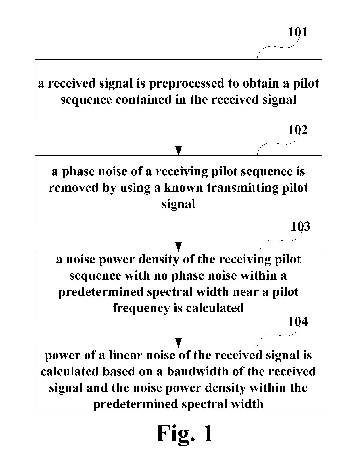
[0044]FIG. 1 is a flowchart of the detection method for noise intensity of Embodiment 1 of this disclosure. As shown in FIG. 1, the detection method for noise intensity includes:

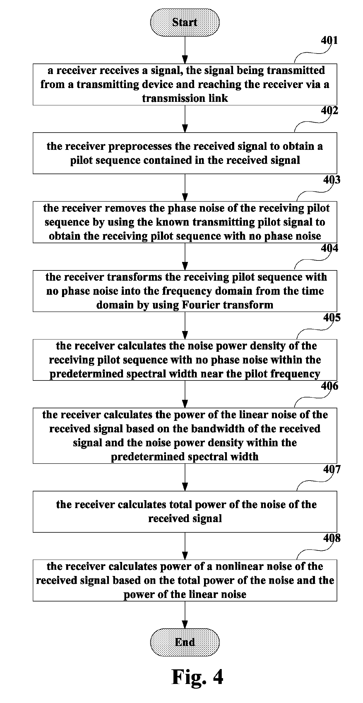
[0045]step 101: a received signal is preprocessed to obtain a pilot sequence contained in the received signal;

[0046]step 102: a phase noise of a receiving pilot sequence is removed by using a known transmitting pilot signal;

[0047]step 103: a noise power density of the receiving pilot sequence with no (or without) phase noise within a predetermined spectral width near a pilot frequency is calculated; and

[0048]step 104: power of a linear noise of the received signal is calculated based on a bandwidth of the received signal and the noise power density within the predetermined spectral width.

[0049]In this embodiment, a pilot sequence may be added into a transmitting signal in a trans...

embodiment 2

[0089]The embodiment of this disclosure provides a detection apparatus for noise intensity, configured in a coherent optical receiver. Contents in this embodiment identical to those in Embodiment 1 shall not be described herein any further.

[0090]FIG. 9 is a schematic diagram of the detection apparatus for noise intensity of the embodiment of this disclosure. As shown in FIG. 9, the detection apparatus 900 for noise intensity includes:

[0091]a signal preprocessing unit 901 configured to preprocess a received signal to obtain a pilot sequence contained in the received signal;

[0092]a phase noise removing unit 902 configured to remove a phase noise of a receiving pilot sequence by using a known transmitting pilot signal;

[0093]a power density calculating unit 903 configured to calculate a noise power density of the receiving pilot sequence with no phase noise within a predetermined spectral width near a pilot frequency; and

[0094]a linear noise calculating unit 904 configured to calculate ...

embodiment 3

[0112]The embodiment of this disclosure provides a coherent optical receiver, which may be configured with the detection apparatus 900 or 1000 for noise intensity described in Embodiment 2. Contents in this embodiment identical to those in embodiments 1 and 2 shall not be described herein any further.

[0113]FIG. 11 is a schematic diagram of the coherent optical receiver of the embodiment of this disclosure. As shown in FIG. 11, the coherent optical receiver 1100 may include:

[0114]an optical-to-electrical converter 1101 configured to convert a received optical signal into an electrical signal; and

[0115]a digital signal processor 1102 configured to preprocess the electrical signal to obtain a pilot sequence contained in the electrical signal, remove a phase noise of a receiving pilot sequence by using a known transmitting pilot signal, calculate a noise power density of the receiving pilot sequence with no phase noise within a predetermined spectral width near a pilot frequency, and ca...


PUM


Abstract

A detection apparatus and method for noise intensity and a coherent optical receiver where the detection method includes: preprocessing a received signal to obtain a pilot sequence contained in the received signal; removing a phase noise of a receiving pilot sequence by using a known transmitting pilot signal; calculating a noise power density of the receiving pilot sequence with no (or without) phase noise within a predetermined spectral width near a pilot frequency; and calculating power of a linear noise of the received signal based on a bandwidth of the received signal and the noise power density within the predetermined spectral width. Hence, linear noises and nonlinear noises may be split efficiently without introducing much complexity, and information on intensities of various noises may be obtained.

Description

CROSS-REFERENCE TO RELATED APPLICATIONS[0001]This application claims the benefit of Chinese Application No. 201610806100.2, filed Sep. 7, 2016, in the Chinese Intellectual Property Office, the disclosure of which is incorporated herein by reference.BACKGROUND1. Field[0002]This disclosure relates to the field of optical communications technologies, and in particular to a detection apparatus and method for noise intensity and a coherent optical receiver.2. Description of the Related Art[0003]In a coherent optical receiver, existence of noises causes transmission performance of a system to be limited. Noises introduced into signal transmission mainly include an amplified spontaneous emission (ASE) noise, a cross-phase modulation (XPM) noise of neighboring channels in a wavelength division multiplexing (WDM) transmission system, and a self-phase modulation (SPM) noise in transmission channels. Such three types of noises are different in physical mechanisms, their relative intensities ar...

Claims


Application Information

Patent Timeline
Patent Type & Authority Patents(United States)
IPC IPC(8): H04W48/18H04B10/079H04B10/61
CPCH04B10/07955H04B10/07953H04B10/6164H04B10/6165H04B10/616H04B2210/075H04B10/0795H04B10/61
Inventor ZHAO, YINGTAO, ZHENNING
Owner FUJITSU LTD
Why Eureka
Try Eureka