Optical relay system and method
A relay system and one-way technology, applied in the field of optical communication, can solve problems such as complex implementation, slow electrical processing speed, and unsuitability for high-speed signal processing, and achieve the effects of simple implementation, phase noise elimination, and improved transmission performance
- Summary
- Abstract
- Description
- Claims
- Application Information
AI Technical Summary
Problems solved by technology
Method used
Image
Examples
Embodiment 1
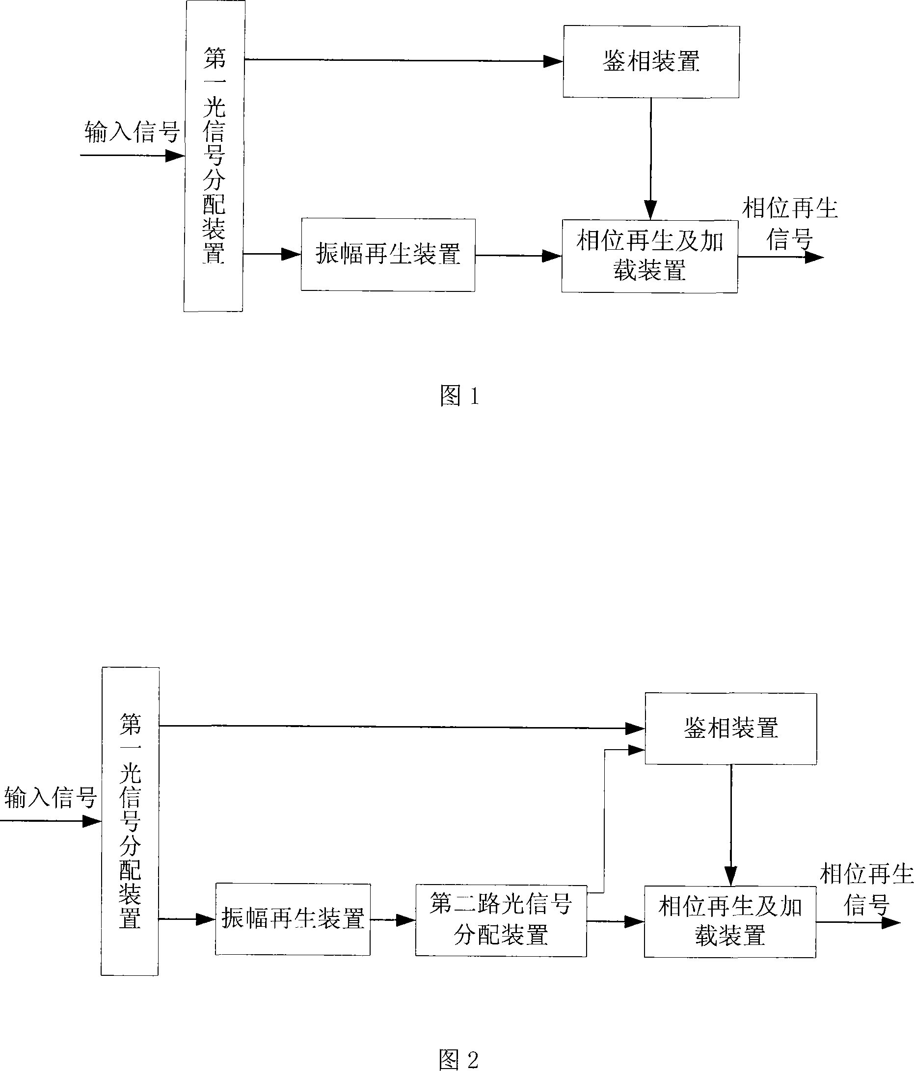
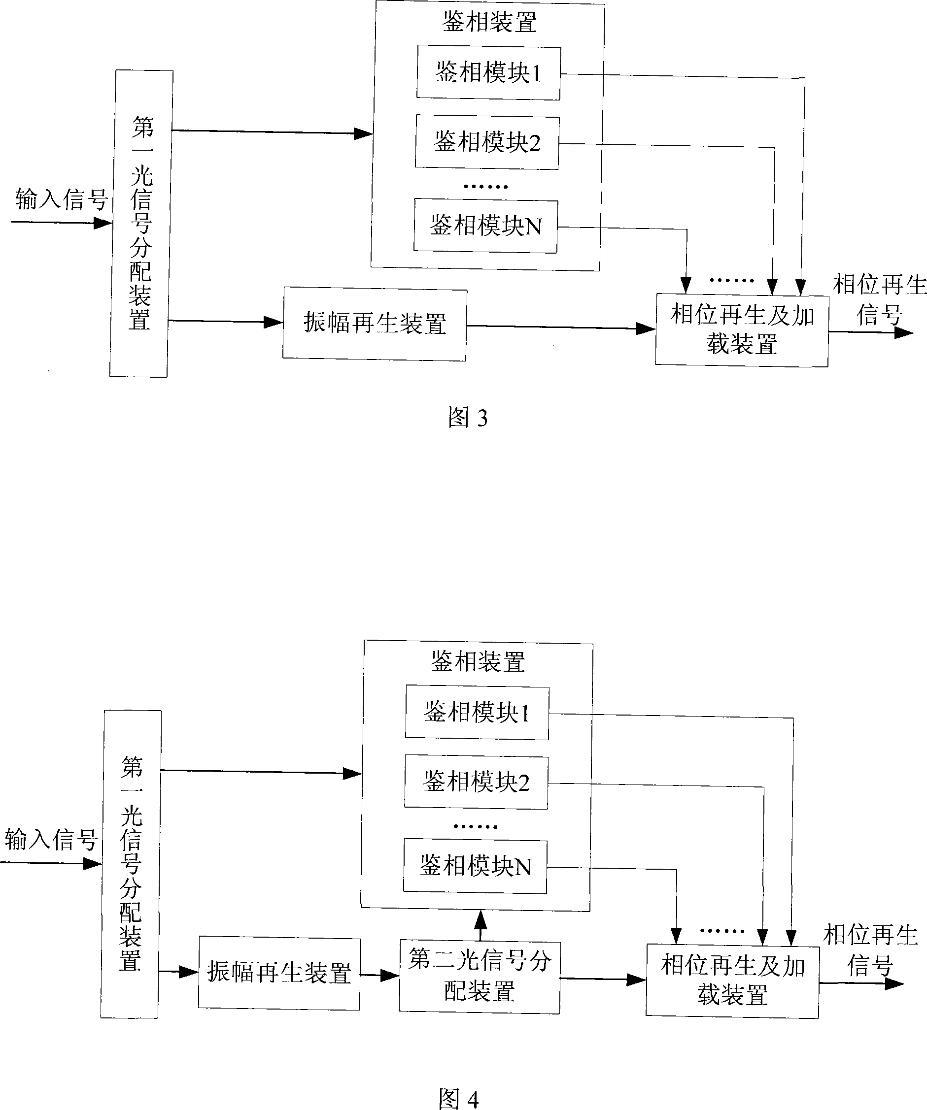
[0050] see figure 1 , this embodiment provides an optical relay system, including:
[0051] The first optical signal distribution device is used to receive the input signal, divide the input signal into a first input signal and a second input signal, and output the first input signal and the second input signal respectively;
[0052] The phase detection device is used to receive the first input signal output by the first optical signal distribution device, extract the phase information of the first input signal, convert the phase information into an amplitude modulation signal, and output the amplitude modulation signal; wherein, the amplitude modulation signal It is the phase information carried on the intensity signal, and it is a high and low level signal, which is used to modulate the phase of the signal;
[0053] The amplitude regeneration device is used for receiving the second input signal output by the first optical signal distribution device, shaping the input signa...
Embodiment 2
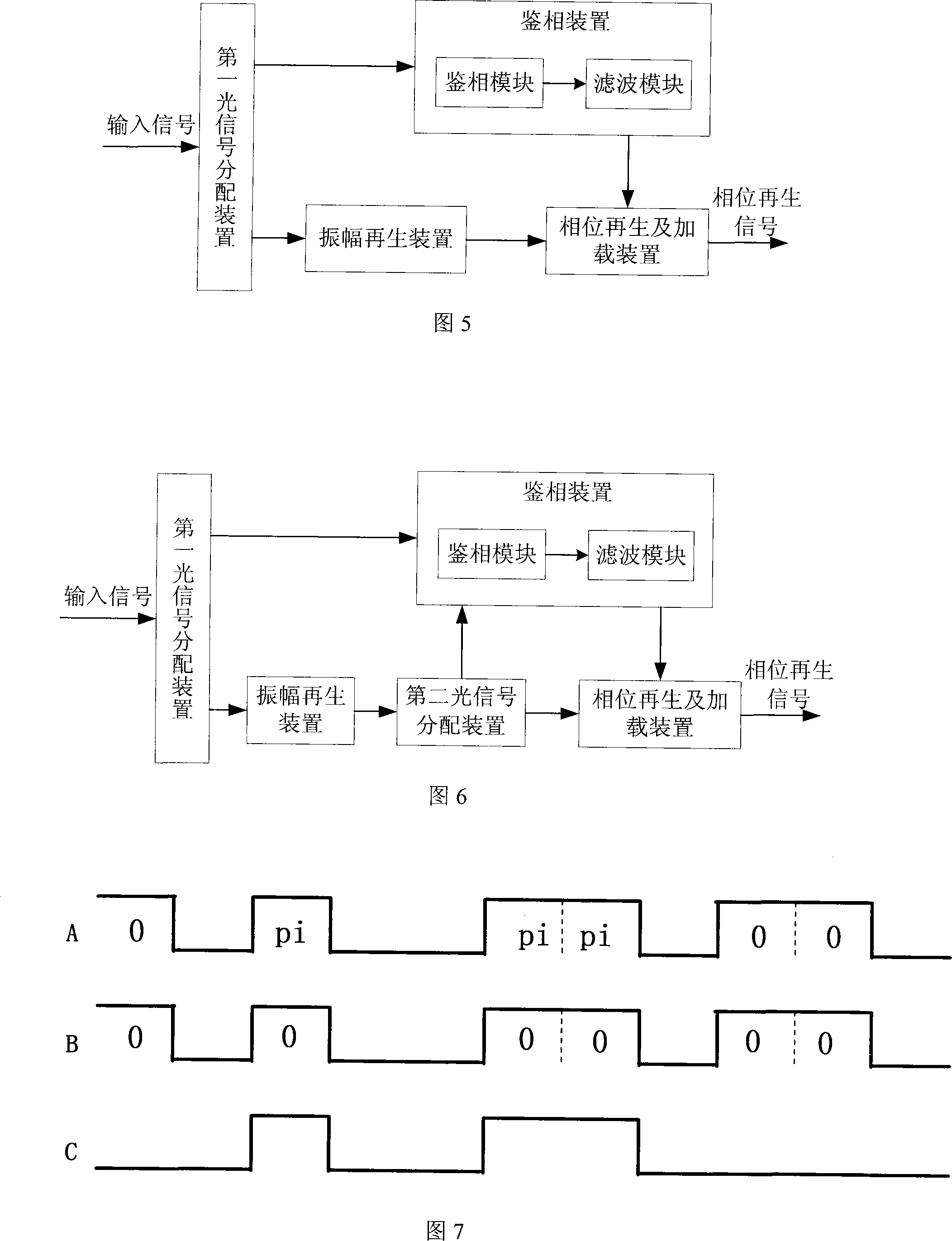
[0059] This embodiment provides an optical relay system. Similar to Embodiment 1, the optical relay system provided by this embodiment also includes: a first optical signal distribution device, a phase detection device, an amplitude regeneration device, and a second optical signal distribution device. Device (optional) and phase regeneration and loading device, the function of each device is the same as embodiment 1, no longer detailed description here, this relay system is used in the all-optical of ODB (Optical Dual Binary, optical double binary) signal continue. see Figure 5 , the phase detection device in this embodiment includes:
[0060] The phase detection module is used to receive the first input signal output by the first optical signal distribution device, extract the phase information of the first input signal, and convert the phase information into an amplitude modulation signal, wherein the amplitude modulation signal is carried by the intensity signal The phas...
Embodiment 3
[0100] This embodiment provides an optical relay system. Similar to Embodiment 1, the optical relay system provided by this embodiment also includes: a first optical signal distribution device, a phase detection device, an amplitude regeneration device, and a second optical signal distribution device. device (optional) and phase regeneration and loading device, the function of each device is the same as embodiment 1, no longer detailed description here, this relay system is used for DPSK (Diffential Phase Shift Keying, differential phase shift keying) signal All-optical relay, see Figure 10 , the amplitude regeneration device of the optical relay system provided in this embodiment includes:
[0101] A continuous light emitting module for providing continuous light;
[0102] The phase calibration module is used to receive the second input signal output by the first optical signal distribution device and the continuous light provided by the continuous light emitting module, pe...
PUM
 Abstract
Description
Claims
Application Information
 - R&D
- Intellectual Property
- Life Sciences
- Materials
- Tech Scout
- Unparalleled Data Quality
- Higher Quality Content
- 60% Fewer Hallucinations
Browse by: Latest US Patents, China's latest patents, Technical Efficacy Thesaurus, Application Domain, Technology Topic, Popular Technical Reports.
© 2025 PatSnap. All rights reserved.Legal|Privacy policy|Modern Slavery Act Transparency Statement|Sitemap|About US| Contact US: help@patsnap.com


