A knocking and stripping device for filter element impurity

A peeling device and filter element technology, which is applied in separation methods, transportation and packaging, dispersed particle separation, etc., can solve the problems of general rapping effect and low practicability, and achieve improved peeling effect, convenient operation and simple overall structure. Effect

Active Publication Date: 2021-02-26
李冰雪
View PDF7 Cites 0 Cited by
  • Summary
  • Abstract
  • Description
  • Claims
  • Application Information

AI Technical Summary

Problems solved by technology

[0003] As disclosed in CN207324310U, a rapping device for a filter core comprises an insulating housing, a coil winding arranged in the insulating housing, an iron ring and an energy storage spring arranged in the middle of the coil winding, and the energy storage spring and the iron ring The inner and outer spaces are arranged, and a fixed shell is closely arranged in front of the energy storage spring and the iron ring, and the energy storage spring is accommodated in the fixed shell; one end of the energy storage spring is fixed on the top of the fixed ring, and the other end is passed through A slider is connected to the upper end of a vibrating hammer, and the lower end of the vibrating hammer passes through the fixed casing and extends down to the top of the filter element. When the coil winding is energized, a magnetic field is generated in the coil winding and acts on the slider and the iron. Ring, because the same polarity produces action force and reaction force, thereby compressing the energy storage spring, the rapping hammer head retracts, and reaches a certain amount of compression to reset the energy storage spring, and the rapping hammer stretches out to vibrate the filter element to achieve a vibration effect , the vibration frequency of the rapping hammer is related to the frequency of the incoming electricity, but it is a single-point percussion, the rapping effect is average, and during the rapping process, manpower is required to turn the filter element over, and personnel are required to follow up in real time, which is not practical powerful

Method used


Image

  • A knocking and stripping device for filter element impurity
  • A knocking and stripping device for filter element impurity

Examples


Embodiment Construction

[0017] The following will clearly and completely describe the technical solutions in the embodiments of the present invention with reference to the accompanying drawings in the embodiments of the present invention. Obviously, the described embodiments are only some, not all, embodiments of the present invention. Based on the embodiments of the present invention, all other embodiments obtained by persons of ordinary skill in the art without making creative efforts belong to the protection scope of the present invention.

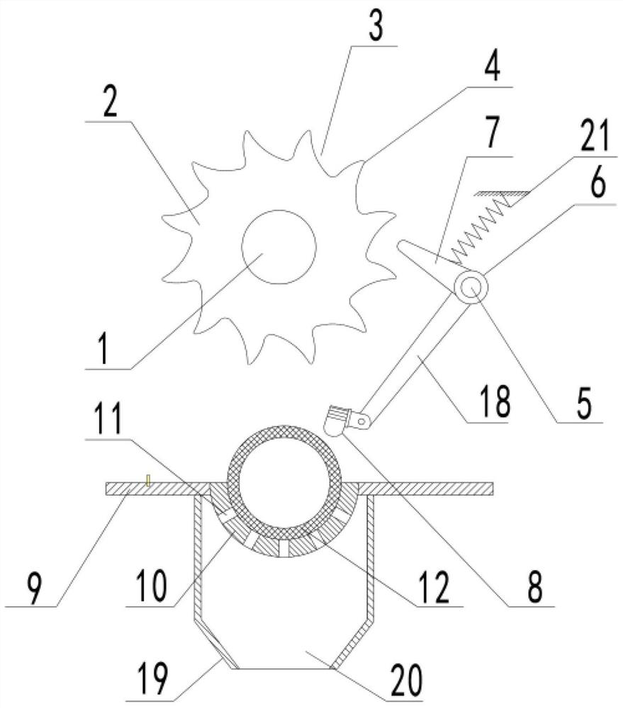
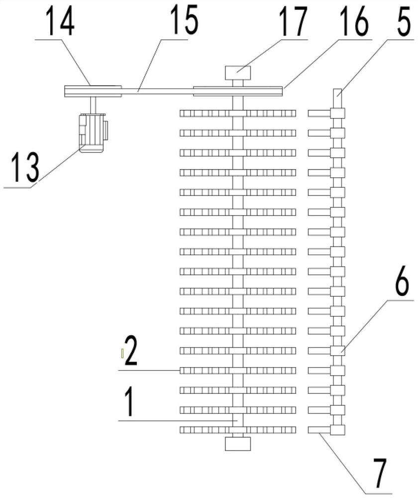
[0018] see Figure 1~2 , in an embodiment of the present invention, a filter impurity knocking and stripping device includes a rotating shaft 1, a power disc 2, an active rod 7, a percussion head 8, a working table 9, a filter element placement plate 10, and a passive rod 18. The power disc 2 is installed on the rotating shaft 1. There are a plurality of teeth 4 on the outer circumference of the power disc 2. The teeth 4 are arc-shaped convex structures. The g...


PUM


Abstract

The invention discloses a device for knocking and stripping filter core impurities, which comprises a rotating shaft, a power disc, an active rod, a percussion head, a working table, a filter element placement plate and a passive rod. The power disc is installed on the rotating shaft, and the outer circumference of the power disc is There are a plurality of teeth on the top, the teeth are arc-shaped convex structures, and the gaps between adjacent teeth are connected. One side of the rotating shaft is provided with a fixed shaft, and the fixed shaft is parallel to the rotating shaft. A shaft sleeve that rotates independently of it is installed, and an active rod and a passive rod are fixed on the outer surface of the shaft sleeve. The beneficial effect of the present invention is that the filter element can be knocked in all directions by setting multiple sets of power discs and knocking heads. , improve the peeling effect of dust and impurities, and under the knocking of the beating head, the filter element can rotate at a certain angle, so that the filter element can be rotated while being knocked, and the peeling effect of dust and impurities is improved. The overall structure is simple, easy to operate, and has the advantages of Very practical.

Description

technical field [0001] The invention relates to a filter element impurity knocking mechanism, in particular to a filter element impurity knocking and stripping device. Background technique [0002] Because a large amount of fine dust will be adsorbed on the filter element during the filtering process of the industrial vacuum cleaner, the dust will greatly affect the dust collection efficiency of the vacuum cleaner, and the function of the vibrating device is to shake off the dust on the filter element to ensure The filter element is clean, and at the same time, the air from the filter element flows out from the inside to the outside to provide assistance for the dust removal of the filter element. [0003] As disclosed in CN207324310U, a rapping device for a filter core comprises an insulating housing, a coil winding arranged in the insulating housing, an iron ring and an energy storage spring arranged in the middle of the coil winding, and the energy storage spring and the ...

Claims


Application Information

Patent Timeline
Patent Type & Authority Patents(China)
IPC IPC(8): B01D46/00
CPCB01D46/76
Inventor 李冰雪
Owner 李冰雪
Why Eureka
Try Eureka