Spray room sludge separator

A technology for separating machines and sludge, which is applied to centrifuges and centrifuges with rotating drums, etc. It can solve the problems of increasing the workload of workers and affecting the working efficiency of machines, and achieves convenient and quick disassembly and assembly, reducing resistance, The effect of reducing kinetic energy loss

Pending Publication Date: 2018-11-09
ZHANGJIAGANG SHENGLITAI CENTRIFUGE MFG
View PDF0 Cites 0 Cited by
  • Summary
  • Abstract
  • Description
  • Claims
  • Application Information

AI Technical Summary

Problems solved by technology

During the working process of the existing sludge separator in the spray booth, the speed of the sludge and water under high-speed rotation is inconsistent, which makes the sludge separator in the spray booth vibrate and make noise, but in the closed barrel, it is impossible to know Whe

Method used


Image

  • Spray room sludge separator
  • Spray room sludge separator
  • Spray room sludge separator

Examples


Embodiment Construction

[0034] Below in conjunction with specific embodiment, content of the present invention is described in further detail:

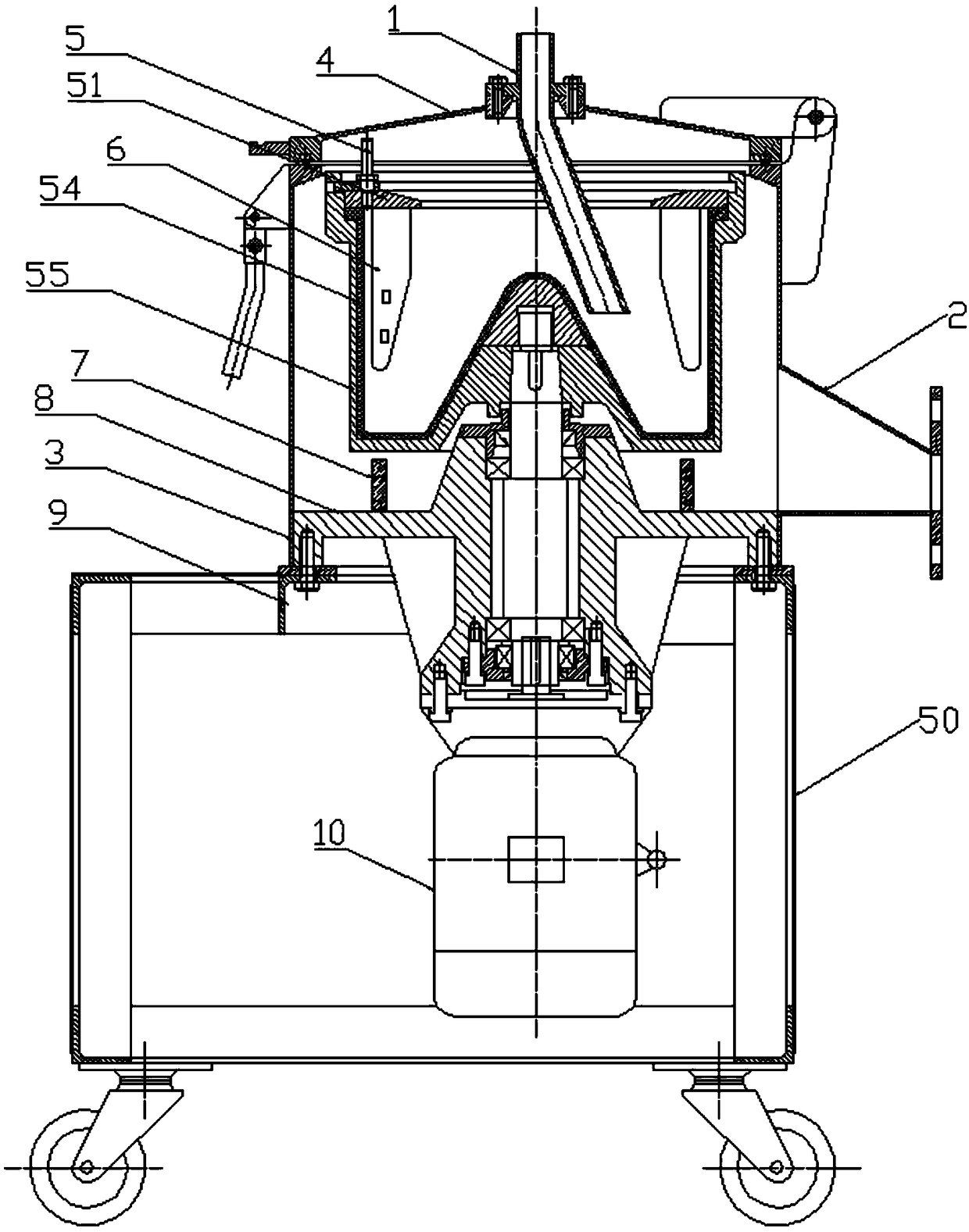
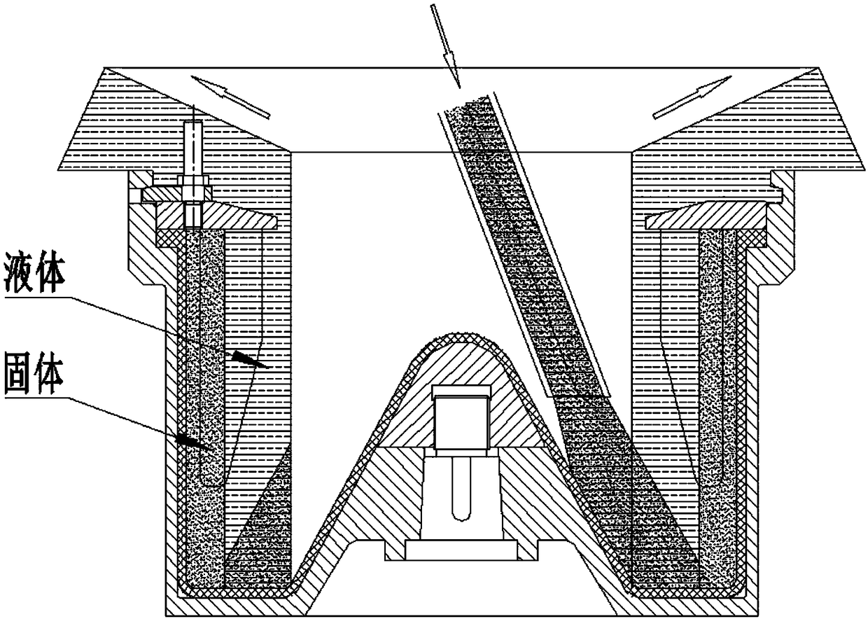
[0035]In order to achieve the purpose of the present invention, one embodiment of the present invention is: a spray booth sludge separator, including a machine base 9, a casing 3, a drum 55 and a driving device, and an organic cover 4 is installed on the casing 3 , a feeding pipe 1 is connected on the machine cover, the drum 55 is driven by the driving device, and the driving device is installed on the machine base 9, a waste liquid recovery chamber is formed between the housing 3 and the drum 55, and one side of the housing 3 is provided There is a liquid discharge port 2, a barrel 54 is installed in the drum 55, a liquid blocking plate 51 is detachably installed on the barrel 54, and at least one synchronous baffle 6 is installed on the liquid blocking plate 51, and the synchronous baffle 6 is installed There is a signal generator capable of detecting full...


PUM


Abstract

The invention discloses a spray room sludge separator. The spray room sludge separator comprises a machine base, a machine shell, a rotating drum and a driving device, wherein the machine shell is provided with a machine cover, and the machine cover is connected with a feeding pipe. The rotating drum is driven by the driving device, and the driving device is mounted on the machine base. A chargingbarrel is mounted in the rotating drum, and a liquid blocking plate is detachably mounted on the charging barrel. The liquid blocking plate is provided with at least one synchronous baffle, and the synchronous baffles are provided with signal generators capable of detecting the full accumulation of sludge in the charging barrel. By arranging a plurality of synchronous baffles on the liquid blocking plate, the synchronous baffles divide the charging barrel into a plurality of regions, so that when the charging barrel rotates at a high speed, solids and liquid inside the charging barrel are easier to rotate synchronously in the regions, and generation of water waves and violent vibration of the rotating drum are avoided. The signal generators can feed back the information after sludge in the charging barrel is collected to prompt workers to clean up.

Description

technical field [0001] The invention relates to a spray booth sludge separator. Background technique [0002] During the working process of the spray booth, the waste water generated needs to be treated in time to prevent the sludge in the waste water from adhering to the surface of related devices. The more environmentally friendly and effective method for treating wastewater is to add a medicament that can coagulate the sludge into the wastewater, and then send it to the wind-jet sludge separator for solid-liquid separation. During the working process of the existing sludge separator in the spray booth, the speed of the sludge and water under high-speed rotation is inconsistent, which makes the sludge separator in the spray booth vibrate and make noise, but in the closed barrel, it is impossible to know Whether the sludge has been collected can only be opened and cleaned after a fixed period of time. It often happens that the machine is still working when the sludge is no...

Claims


Application Information

Patent Timeline
IPC IPC(8): B04B1/00B04B9/02B04B13/00B04B15/00B04B11/04
CPCB04B1/00B04B9/02B04B11/04B04B13/00B04B15/00
Inventor 沈峰丁爱兵
Owner ZHANGJIAGANG SHENGLITAI CENTRIFUGE MFG
Why Eureka
Try Eureka