Eureka AIR delivers breakthrough ideas for toughest innovation challenges, trusted by R&D personnel around the world.

Tooling for machining internal sinking amount of piston ring and using method thereof

A piston ring and tooling technology, applied in the field of tooling and fixtures, can solve the problems of low production efficiency, time-consuming and labor-intensive, etc., and achieve the effects of high processing quality, accurate installation position, and high automation level.

Active Publication Date: 2018-11-09
CRRC CHANGZHOU DIESEL ENGINE COMPONENTS CO LTD +1
View PDF6 Cites 2 Cited by
  • Summary
  • Abstract
  • Description
  • Claims
  • Application Information

AI Technical Summary

Problems solved by technology

[0003] The purpose of the present invention is to overcome the time-consuming and labor-intensive defects of the prior art in processing piston rings, and to provide a piston ring with a certain amount of sinking, which can be formed by cold bending with tooling. Time-saving and labor-saving, high automation level, tooling for processing piston ring inner sinking and its use method which improves production efficiency

Method used


Image

  • Tooling for machining internal sinking amount of piston ring and using method thereof
  • Tooling for machining internal sinking amount of piston ring and using method thereof
  • Tooling for machining internal sinking amount of piston ring and using method thereof

Examples


Embodiment Construction

[0036] The present invention is described in further detail now in conjunction with accompanying drawing. These drawings are all simplified schematic diagrams, which only illustrate the basic structure of the present invention in a schematic manner, so they only show the configurations related to the present invention.

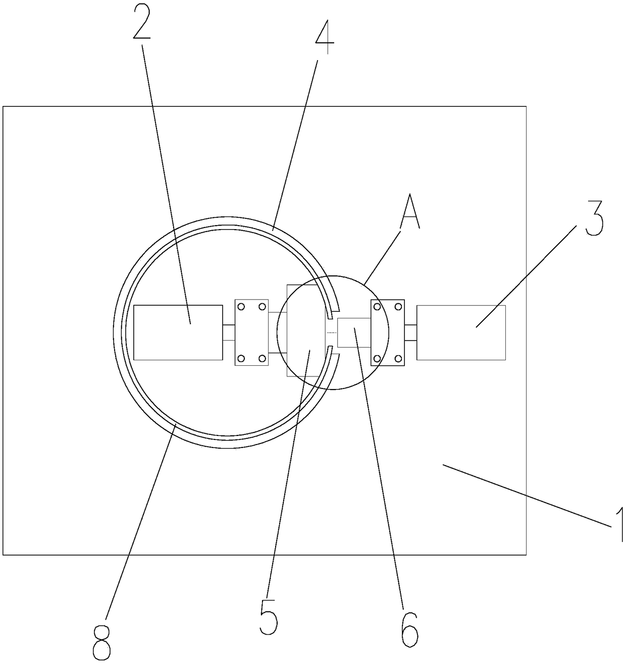
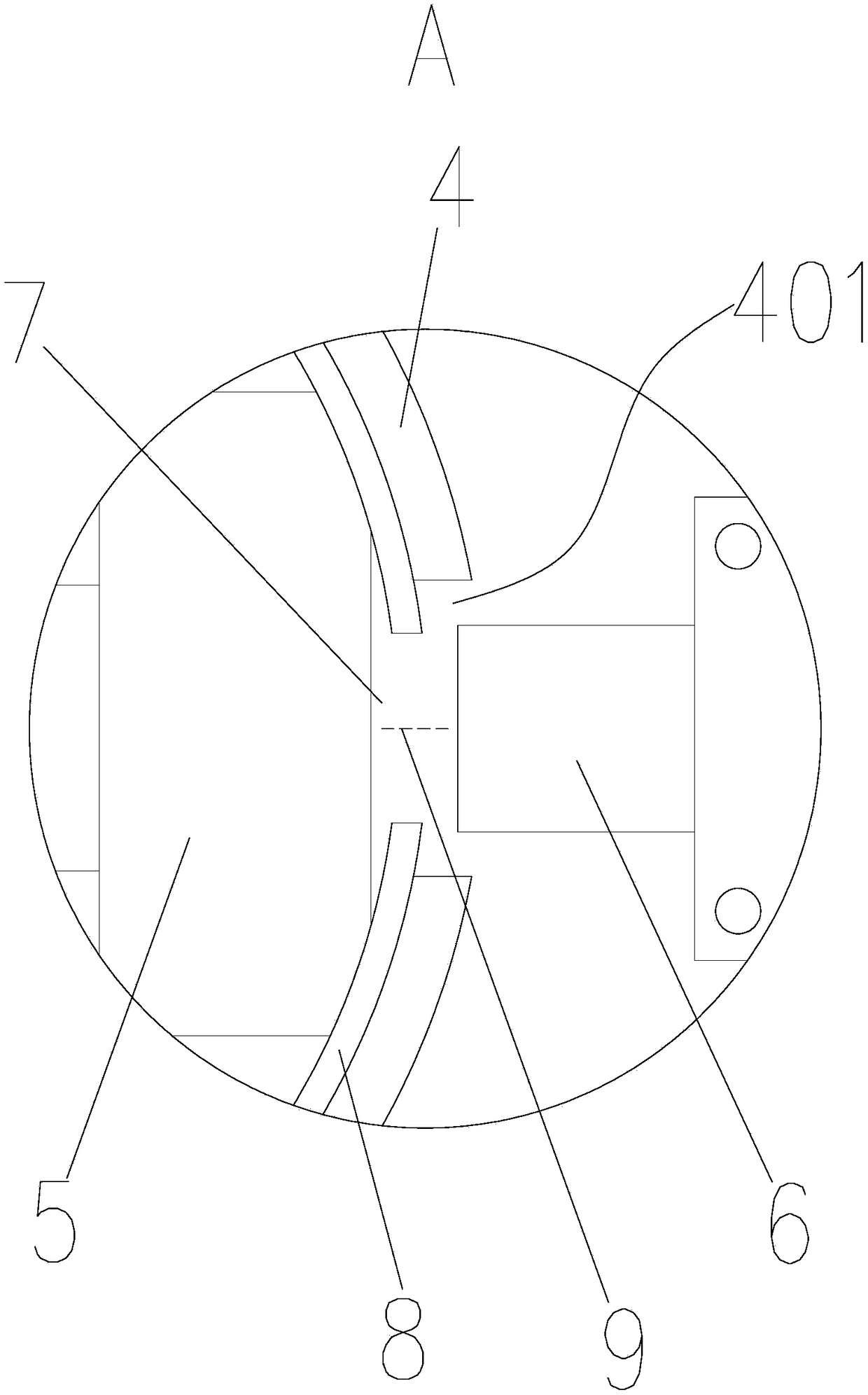
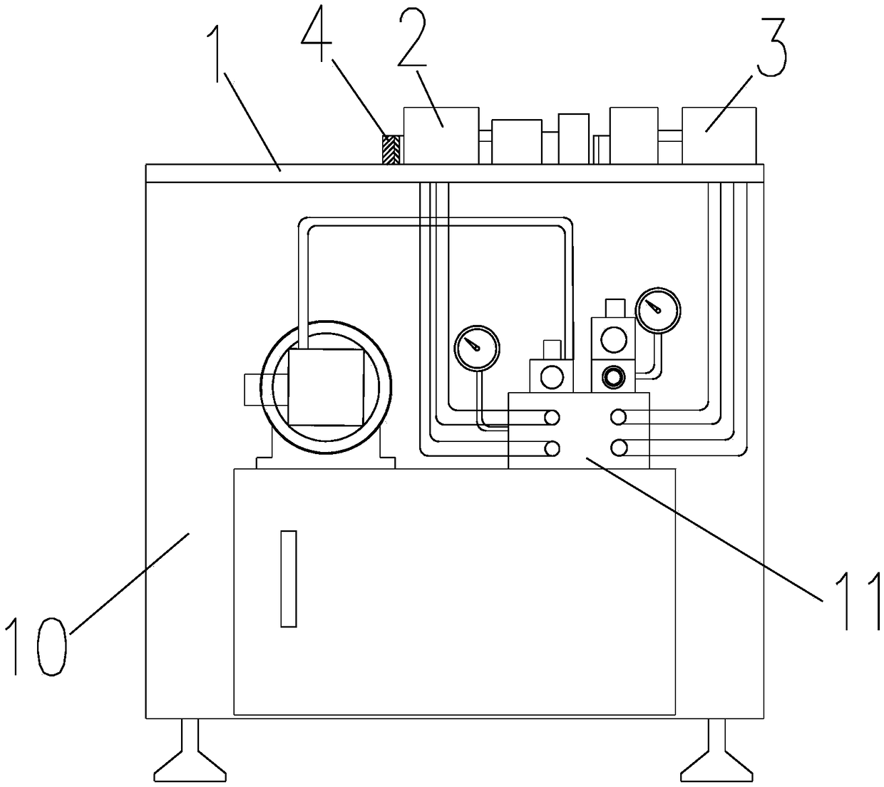
[0037] Such as Figure 1-Figure 4 Shown is a specific embodiment of the tooling used for machining the inner weight of piston rings of the present invention, which includes an operating table 1, on which a clamping cylinder 2, a working cylinder 3, and a hoop are fixed on the The positioning ring gauge 4 on the outside of the piston ring 8, the clamping cylinder 2 is set on the inside of the positioning ring gauge 4, the work inlet cylinder 3 is set on the outside of the positioning ring gauge 4, and the circumferential surface of the positioning ring gauge 4 is provided with a top pressure gap 401. The piston extension end of the tight oil cylinder 2 is fixe...


PUM


Abstract

The invention belongs to the field of tooling fixtures, and particularly relates to a tooling for machining internal sinking amount of a piston ring and a using method thereof. The tooling comprises acontrol console, and a clamping oil cylinder, a working feed cylinder and a positioning ring gauge are fixed on the control console; the clamping oil cylinder is disposed on the inner side of the positioning ring gauge, the working feed oil cylinder is disposed on the outer side of the positioning ring gauge, and a top pressure notch is formed in the circumference surface of the positioning ringgauge; an inner top block is fixed to the extension end of a piston of the clamping oil cylinder, and an outer top block is fixed to the extension end of a piston of the working feed oil cylinder; thewidth of the inner top block, the length of the top pressure notch and the width of the outer top block are successively decreased, and an internal sinking gap is formed between the cambered surfacesof the inner top block and the top pressure notch in the top pressure state; and the internal sinking gap is greater than the radial direction thickness of the piston ring. The tooling has the beneficial effects that the tooling can be used for manufacturing and forming by cold bending, and the piston ring with a certain internal sinking amount is obtained, time and labor are saved, automation level is high, and production efficiency is improved.

Description

technical field [0001] The invention belongs to the field of tooling fixtures, and in particular relates to a tooling used for processing the inner sinkage of piston rings and a using method thereof. Background technique [0002] In terms of engineering, some special piston rings are designed with inward sinking, that is, in the cold state, the two ends of the piston ring opening are slightly recessed inward for a certain distance. In the working state, it expands when heated, and it will fit the inner wall of the cylinder liner again. At present, there is no equipment and technology for processing the inner sinking of piston rings at home and abroad. It is often bent by hand, which is time-consuming and laborious, and the production efficiency is low, and the size of the inner sinking is not easy to control. Contents of the invention [0003] The purpose of the present invention is to overcome the defects of time-consuming and labor-intensive processing of piston rings i...

Claims


Application Information

Patent Timeline
Patent Type & Authority Applications(China)
IPC IPC(8): B21D53/16B21D11/10B21D11/22
CPCB21D11/10B21D11/22B21D53/16
Inventor 王志伟茆骏亚肖静岚李杨绪
Owner CRRC CHANGZHOU DIESEL ENGINE COMPONENTS CO LTD
Why Eureka
Eureka Blog
Learn More