Manufacturing method and application of hydrophobic/light-trapping fly-eye lens array with micro-nano two-stage structure

A technology of microlens array and fly-eye lens, which is applied in applications, household appliances, optical components, etc., can solve the problems of narrow material selection range, cumbersome process, and harsh conditions, and achieve easy operation of the process, broad application prospects, and simple and easy manufacturing methods line effect

Active Publication Date: 2018-11-09
SOUTH CHINA UNIV OF TECH
View PDF6 Cites 18 Cited by
  • Summary
  • Abstract
  • Description
  • Claims
  • Application Information

AI Technical Summary

Problems solved by technology

Most of the first four methods have problems such as cumbersome process, harsh conditions, high cost and narrow range of material selection, while the template method is considered to be an ideal method for large-scale preparation of fly-eye lens arrays.
However, how to manufacture complex micro-nano structure templates, accurately replicate the micro-nano structure of the template, and make the replicated micro-nano structure demould smoothly are the main challenges for large-scale manufacturing of fly-eye lens arrays.

Method used


Image

  • Manufacturing method and application of hydrophobic/light-trapping fly-eye lens array with micro-nano two-stage structure
  • Manufacturing method and application of hydrophobic/light-trapping fly-eye lens array with micro-nano two-stage structure
  • Manufacturing method and application of hydrophobic/light-trapping fly-eye lens array with micro-nano two-stage structure

Examples


Embodiment Construction

[0038] The present invention will be further described in detail below in conjunction with specific embodiments.

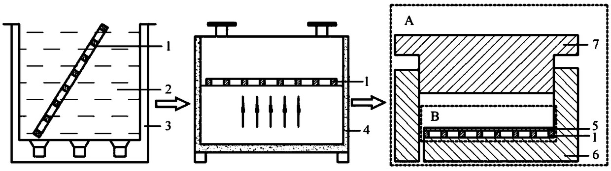
[0039] figure 1 The schematic diagram showing the process of manufacturing the flexible microlens array template of the present invention and fixing it on the surface of the injection mold cavity. The porous plate 1 with a through hole diameter of 250 μm and a hole spacing of 320 μm was immersed in absolute ethanol 2 for ultrasonic cleaning for 20 minutes, and then placed in an oven 4 for drying. The flexible film 5 is closely adhered to one side of the cleaned and dried perforated plate 1 to form a flexible microlens array template B. Fix the flexible microlens array template B on the cavity surface of the fixed mold 6 in the injection mold A.

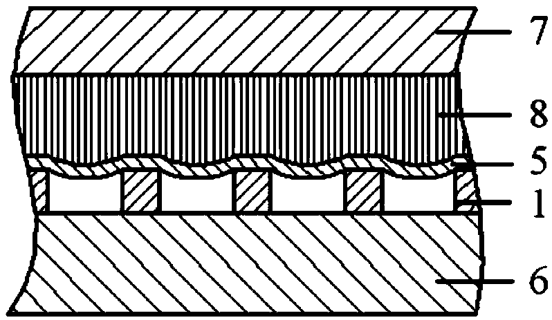
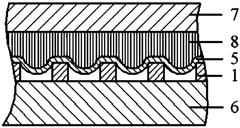
[0040] Figure 2a~2c It shows a schematic diagram of the process of manufacturing a PS product with a microlens array on the surface by the injection molding method of the present invention. Heat the injection mold A, use th...


PUM

PropertyMeasurementUnit
thicknessaaaaaaaaaa
thicknessaaaaaaaaaa
reflectanceaaaaaaaaaa

Abstract

The invention discloses a manufacturing method and application of a hydrophobic / light-trapping fly-eye lens array with a micro-nano two-stage structure, belonging to the field of fly-eye lens arrays and manufacturing technology thereof. The manufacturing method for a high-molecular product of the fly-eye lens array comprises the following steps: manufacturing a flexible microlens array template; fixing the flexible microlens array template onto the surface of the cavity of an injection mold, and molding a microlens array product through injection molding; coining a microlens array on the product onto the surface of an ultra-pure aluminum foil, and then forming nanopores in the surface of the aluminum foil through anodization so as to obtain a fly-eye lens array template with a micro-nano two-stage structure; and fixing the fly-eye lens array template onto the surface of the cavity of the injection mold, and molding the fly-eye lens array product through injection molding. The surface of the fly-eye lens array product has a micro-nano two-stage structure; that is, the surface has both regularly arranged microlens arrays and densely-arranged nano-pillar structures, so the fly-eye lens array product presents hydrophobic and light-trapping characteristics.

Description

Technical field [0001] The invention relates to a fly-eye lens array and its manufacturing technology, in particular to a method and its application for manufacturing a fly-eye lens array with a micro-nano bi-level structure on the surface by injection molding technology to present hydrophobic and light trapping properties. Background technique [0002] With the continuous development of science and technology, miniaturization, integration, and arraying have become important directions for the development of optical systems. In the design and manufacture of micro-nano optical components, nature has given mankind a lot of important enlightenment. The compound eye lens array is a typical example of drawing inspiration from the compound eye of insects. The bionic compound eye lens array has outstanding advantages such as large field of view, high sensitivity, and high integration, which to a large extent compensates for the shortcomings of binocular vision such as small field of vie...

Claims


Application Information

Patent Timeline
Patent Type & Authority Applications(China)
IPC IPC(8): B29C45/00B29C45/26B29L11/00
CPCB29C45/00B29C45/26B29C2045/0094B29K2025/04B29K2025/06B29K2995/0094B29K2995/0097B29L2011/0016B29C45/263B29C45/561B29C45/73B29C33/3842B29D11/00298
Inventor 黄汉雄谢恒
Owner SOUTH CHINA UNIV OF TECH
Why Eureka
Try Eureka