Electric injecting table mechanism for double-lead-screw injection

A technology of double screw and injection table, applied in the field of injection molding mechanism, can solve the problems of high cost and large volume

Pending Publication Date: 2018-11-09
DONGHUA MACHINERY
View PDF0 Cites 3 Cited by
  • Summary
  • Abstract
  • Description
  • Claims
  • Application Information

AI Technical Summary

Problems solved by technology

[0002] At present, the injection mechanism of the electric injection station of the medium and large injection molding machine in the market generally has a structure of three major plates. The injection station part includes the front plate of the injection station, the movable The tie rod of the injection platform is fixed, the movable plate of the injection platform moves between the front plate of the injection platform and the tail plate of the injection platform, the pressure sensor is installed and fixed on the movable plate of the injection platform, the ball screw is fixed on the tail plate of the injection platform, the screw nut and the pressure sensor Fixed connection, the injection movement process is the rotation of the screw, pushing the nut and the movable plate to reciprocate to realize the injection and pumping action during the injection process. At the same time, in order to obtain a larger injection force, it is often driven by double servo motors. The transmission method of double screw rods, this structure is relatively large in size, and the cost of materials required is relatively high

Method used


Image

  • Electric injecting table mechanism for double-lead-screw injection
  • Electric injecting table mechanism for double-lead-screw injection
  • Electric injecting table mechanism for double-lead-screw injection

Examples


Embodiment Construction

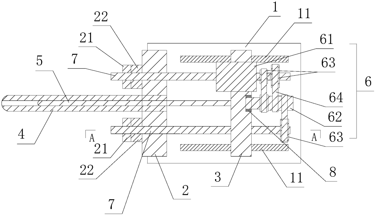
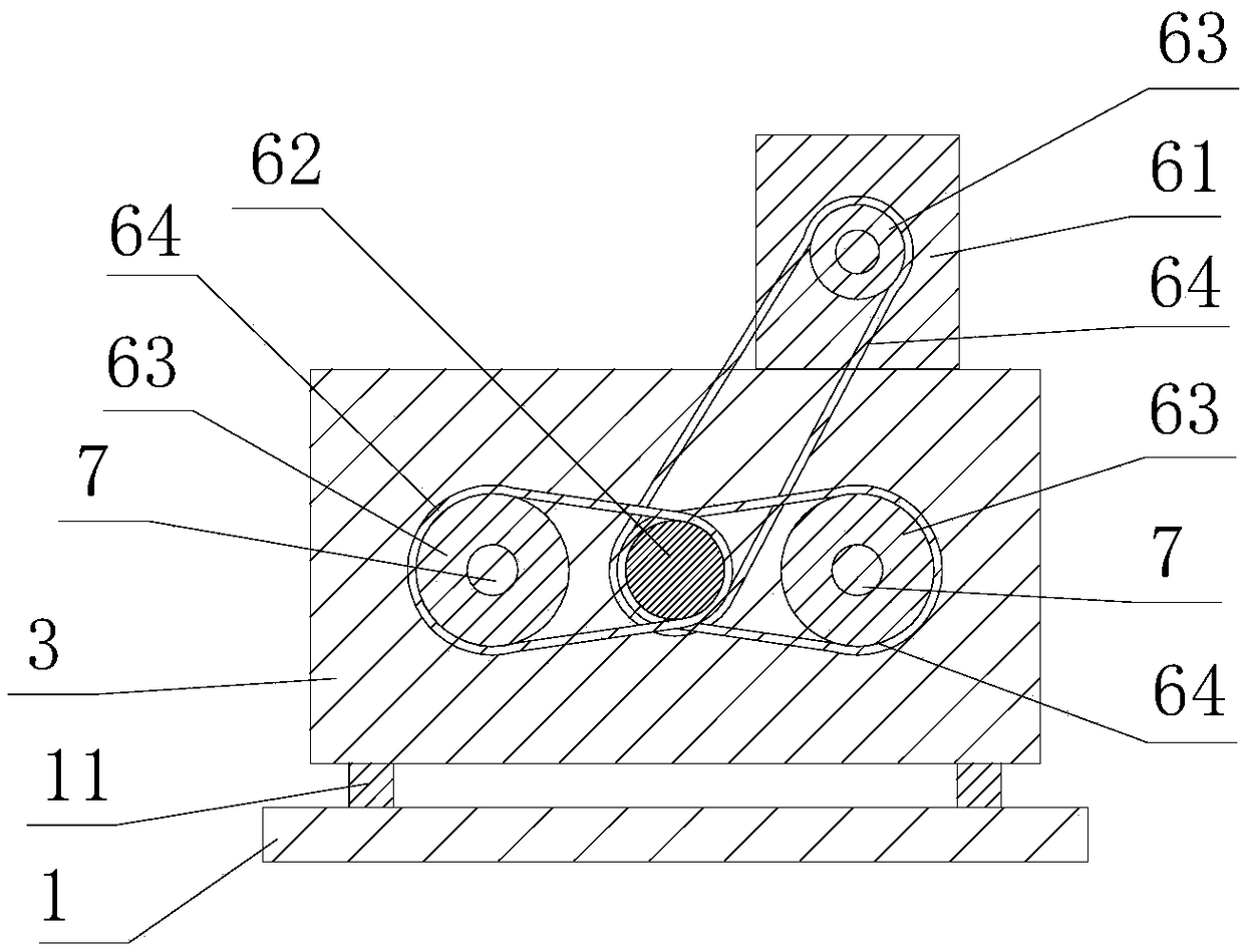
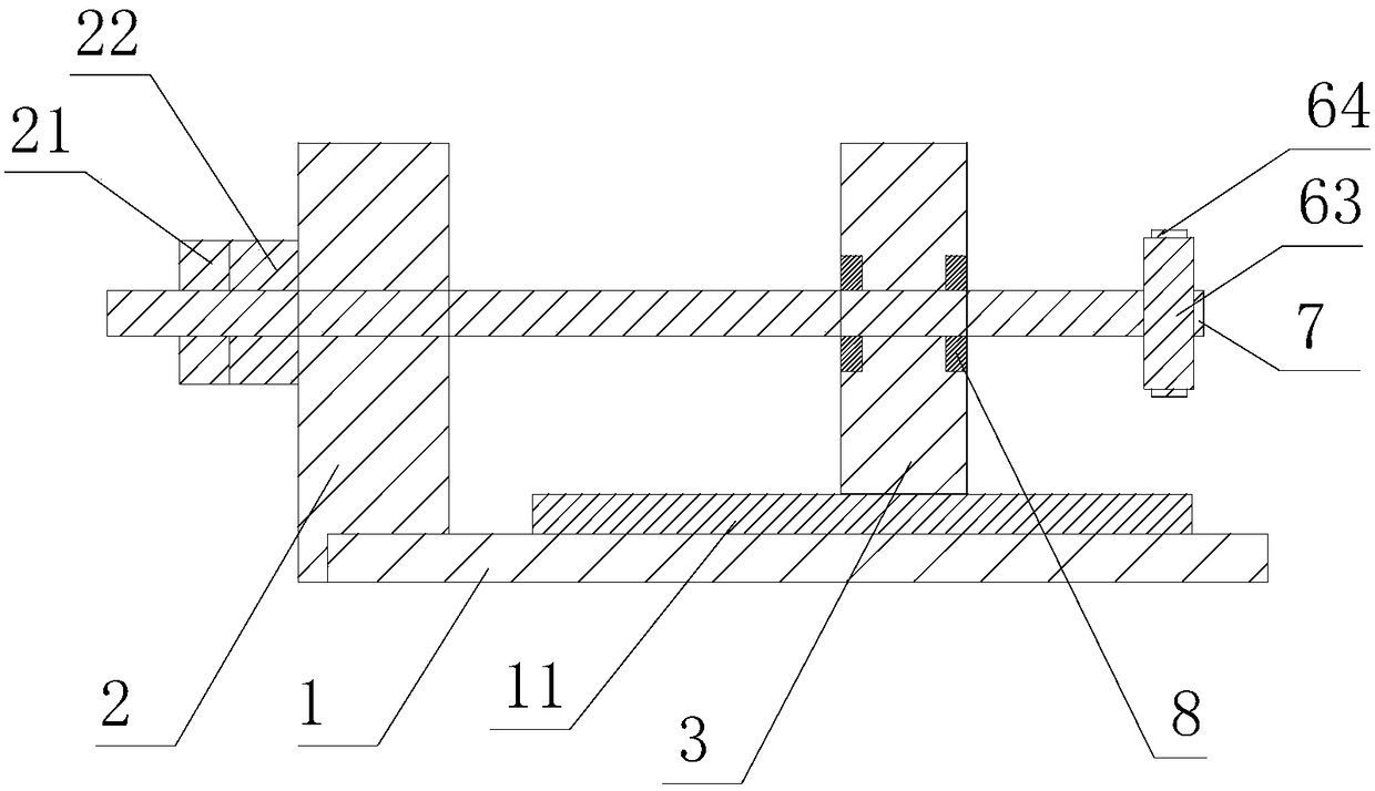
[0018] Such as Figures 1 to 4 As shown, an electric injection platform mechanism for double-screw injection includes an injection platform fixed plate 2 and an injection platform movable plate 3 on a base 1, and a melt rubber cylinder 4 is arranged on the injection platform fixed plate 2, wherein: the injection platform is movable The plate 3 is provided with an electric drive device 6, and the injection platform fixed plate 2 and the injection platform movable plate 3 are provided with an injection screw 5 and ball screws 7 on both sides of the injection screw 5, and the injection screw 5 and ball screws 7 The rotation is positioned in the movable plate 3 of the injection platform, the glue injection screw 5 is interspersed in the melt cylinder 4, the electric drive device 6 is connected with the glue injection screw 5 and the ball screw 7 and rotates simultaneously, the fixed plate 2 of the injection platform is provided with a nut 21, the ball The free end of the screw man...


PUM


Abstract

The invention discloses an electric injecting table mechanism for double-lead-screw injection. The electric injecting table mechanism comprises an injecting table fixed plate and an injecting table movable plate which are located on a base. The injecting table fixed plate is internally provided with a glue melting barrel. The injecting table fixed plate is provided with an electric driving device.A glue injecting screw and ball lead screws on the two sides of the glue injecting screw are arranged between the injecting table fixed plate and the injecting table movable plate. The glue injectingscrew and the ball lead screws are rotationally positioned in the injecting table movable plate. The glue injecting screw is inserted in the glue melting barrel in a penetrating mode. The electric driving device is connected with the glue injecting screw and simultaneously rotates with the ball lead screws. The injecting table fixed plate is provided with nuts. The free ends of the ball lead screws are in threaded connection with the nuts. The injecting table movable plate can linearly move along the base relative to the injecting table fixed plate. The electric injecting table mechanism fordouble-lead-screw injection is simple in structure, and large glue injecting force is obtained through only one servo motor.

Description

technical field [0001] The invention relates to an injection molding mechanism, in particular to an electric injection platform mechanism for twin-screw injection. Background technique [0002] At present, the injection mechanism of the electric injection station of the medium and large-scale injection molding machine in the market generally has a structure of three major plates. The injection station part includes the front plate of the injection station, the movable The tie rod of the injection platform is fixed, the movable plate of the injection platform moves between the front plate of the injection platform and the tail plate of the injection platform, the pressure sensor is installed and fixed on the movable plate of the injection platform, the ball screw is fixed on the tail plate of the injection platform, the screw nut and the pressure sensor Fixed connection, the injection movement process is the rotation of the screw, pushing the nut and the movable plate to do r...

Claims


Application Information

Patent Timeline
IPC IPC(8): B29C45/50
CPCB29C45/5008B29C2045/5056
Inventor 谢雄飞蔡国强
Owner DONGHUA MACHINERY
Why Eureka
Try Eureka