Water containing plate for heat exchanger

A water tray and heat exchanger technology, applied in the field of heat exchangers, can solve the problems of large power consumption, leakage, spillage, etc., and achieve the effects of avoiding secondary freezing, reducing manufacturing costs, and ensuring normal operation

Pending Publication Date: 2018-11-09
GUANGDONG HIWAVE TECH
View PDF7 Cites 2 Cited by
  • Summary
  • Abstract
  • Description
  • Claims
  • Application Information

AI Technical Summary

Problems solved by technology

[0003] The existing way to solve the freezing problem of the water tray is generally to install electric auxiliary heating parts around the water tray, and prevent or solve the freezing problem of the water tray through the heating of the heating parts. The existing water tray mainly uses Drainage of the drain structure, this method has the phenomenon that the drainage of the drain is not complete, which is easy to cause secondary freezing, and the drainage is carried out through the drain, causing the water to spill around and splash on the electronic components when draining; and the use of electric assist The heating of the heating parts consumes a lot of electric energy, which is contrary to the purpose of energy saving of the equipment, and also increases the cost of use. In addition, the electric auxiliary heating is easy to damage and leak electricity after soaking in water for a long time, which will cause the machine to be electrified and pose a certain threat to personal safety.

Method used


Image

  • Water containing plate for heat exchanger
  • Water containing plate for heat exchanger
  • Water containing plate for heat exchanger

Examples


Embodiment Construction

[0025] The present invention is further described in conjunction with the following examples.

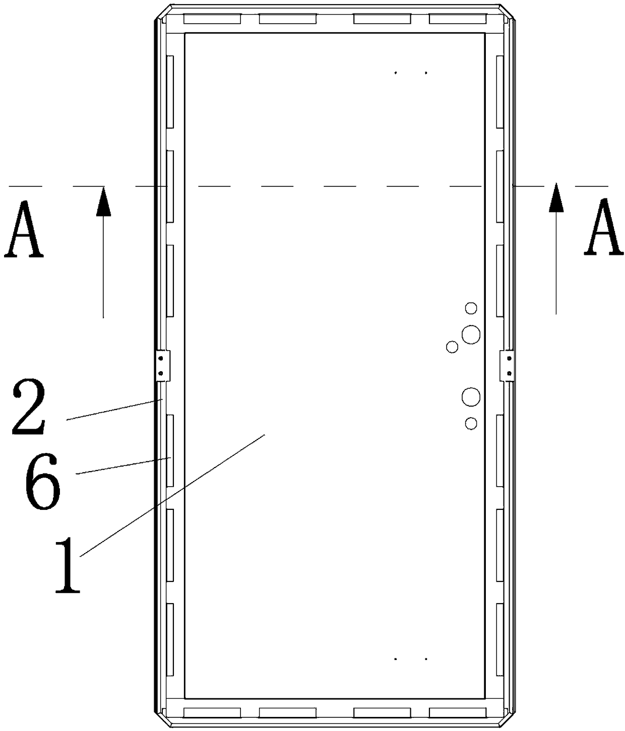
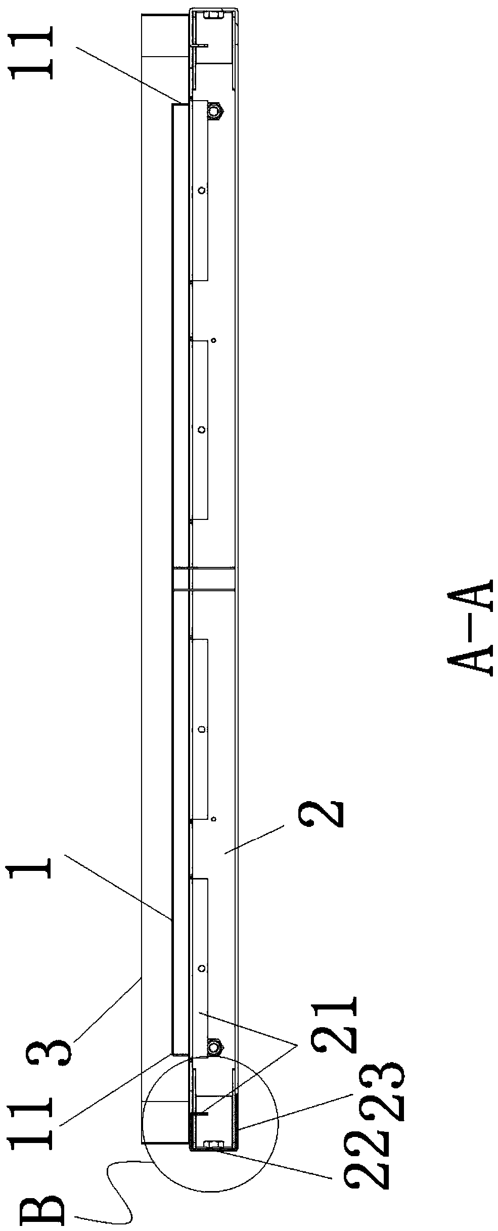
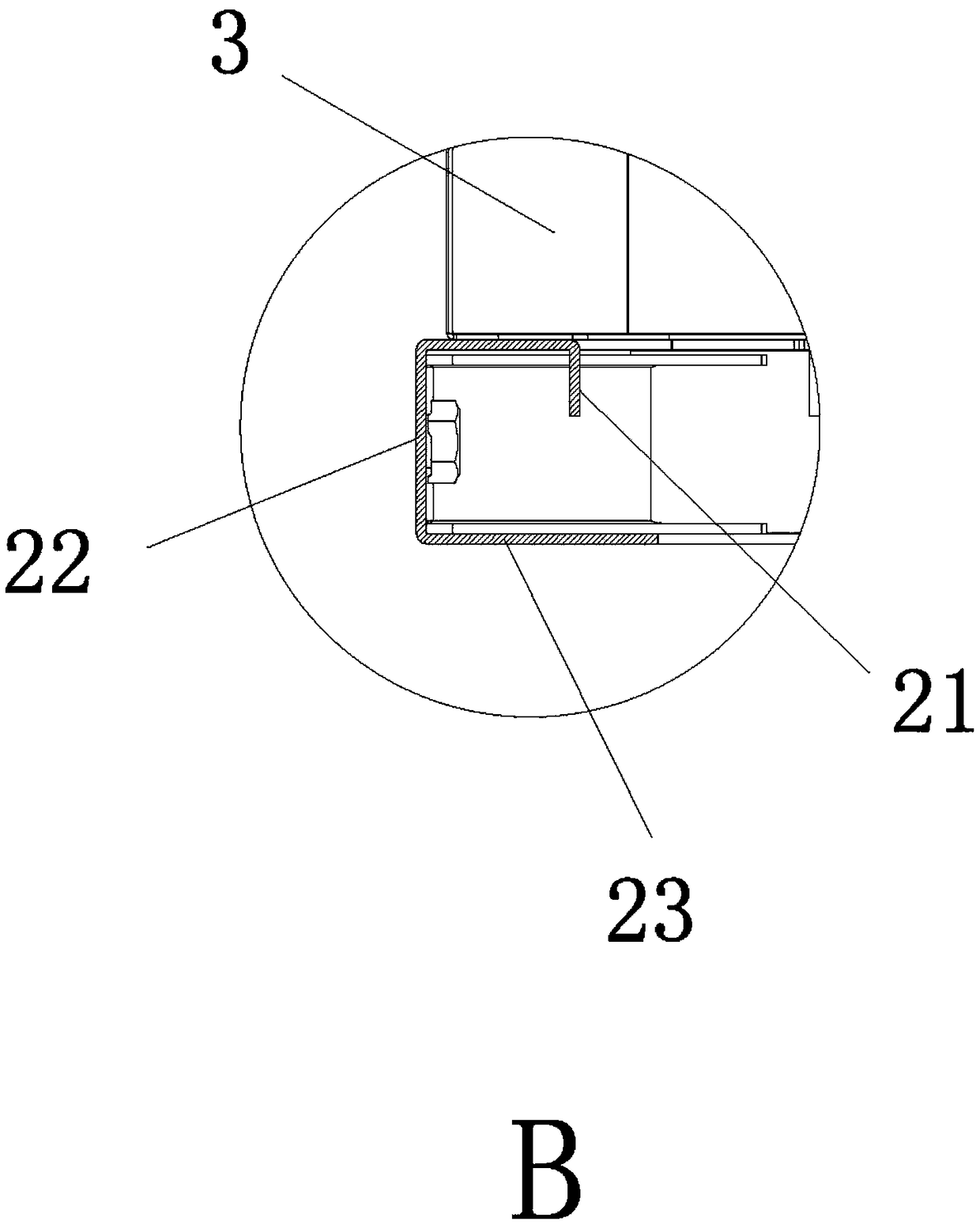
[0026] A specific embodiment of a water receiving tray for a heat exchanger of the present invention, as Figure 1 to Figure 6 As shown, it includes a bottom plate 1 and a water guiding plate 2, the water guiding plate 2 is arranged around the outer periphery of the bottom plate 1 and is detachably connected with the bottom plate 1. In this embodiment, the bottom plate 1 is arranged in a rectangular shape. Of course, the bottom plate 1 is also It can be called circular, triangular and other shapes, and the shape of the water guide plate 2 can be assembled according to the shape of the bottom plate 1. Among them, in order to facilitate the mass production of the water receiving tray, the difficulty of assembling and producing the water receiving tray is simplified , there are four water guide plates 2, and the four water guide plates 2 together form a rectangle. Of course, in additio...


PUM


Abstract

The invention relates to the technical field of heat exchangers, in particular to a water containing plate for a heat exchanger. The water containing plate for the heat exchanger comprises a bottom plate and a water guiding plate, wherein the water guiding plate is arranged on the periphery of the bottom plate in a surrounding way and can be detachably connected with the bottom plate; multiple first notches are arranged on the peripheral side of the bottom plate; the water guiding plate is provided with multiple second notches corresponding to the first notches; the first notches and the corresponding second notches enclose to form multiple drain holes for draining; and a hole wall of each drain hole downwards extends out of a flow guiding part. Compared with the prior art, the multiple drain holes are formed between the water guiding plate and the bottom plate and are formed in the periphery of the bottom plate in a surrounding way, the drain holes extend out of the flow guiding part,and during a draining process, the partial adhesion capacity and the surface tension of water are eliminated through the flow guiding part, so that defrosting water and condensation water can be drained out of the water containing plate along the flow guiding part, the water can be drained smoothly, and the occurrence of the phenomenon that the drain holes are secondarily frozen is avoided; and in addition, an electric auxiliary heating part can be omitted, so that the manufacturing cost is reduced, and the potential safety hazard is eliminated.

Description

technical field [0001] The invention relates to the technical field of heat exchangers, in particular to a water receiving tray for a heat exchanger. Background technique [0002] The heat exchanger of the air conditioner generally produces condensed water when it is working, and the condensed water will flow along the surface of the heat exchange tube on the heat exchanger to the bottom of the heat exchanger, so the bottom of the heat exchanger is generally equipped with a water collector Pan structure, the water pan structure is used to catch the condensed water on the heat exchanger and discharge it through the pipeline. [0003] The existing way to solve the freezing problem of the water tray is generally to install electric auxiliary heating parts around the water tray, and prevent or solve the freezing problem of the water tray through the heating of the heating parts. The existing water tray mainly uses Drainage of the drain structure, this method has the phenomenon ...

Claims


Application Information

Patent Timeline
Patent Type & Authority Applications(China)
IPC IPC(8): F24F13/22
CPCF24F13/222
Inventor 陈以评李福水吕东建
Owner GUANGDONG HIWAVE TECH
Why Eureka
Try Eureka