Display panel, manufacturing method thereof, display device and splicing screen

A display panel and splicing screen technology, which is applied in the direction of identification devices, nonlinear optics, instruments, etc., can solve the problems of destroying image continuity, affecting display and viewing effects, and cannot be completely eliminated, so as to reduce the difficulty of production and increase the process. Difficulty, the effect of reducing the area

Active Publication Date: 2018-11-09
SHANGHAI AVIC OPTOELECTRONICS
View PDF8 Cites 44 Cited by
  • Summary
  • Abstract
  • Description
  • Claims
  • Application Information

AI Technical Summary

Problems solved by technology

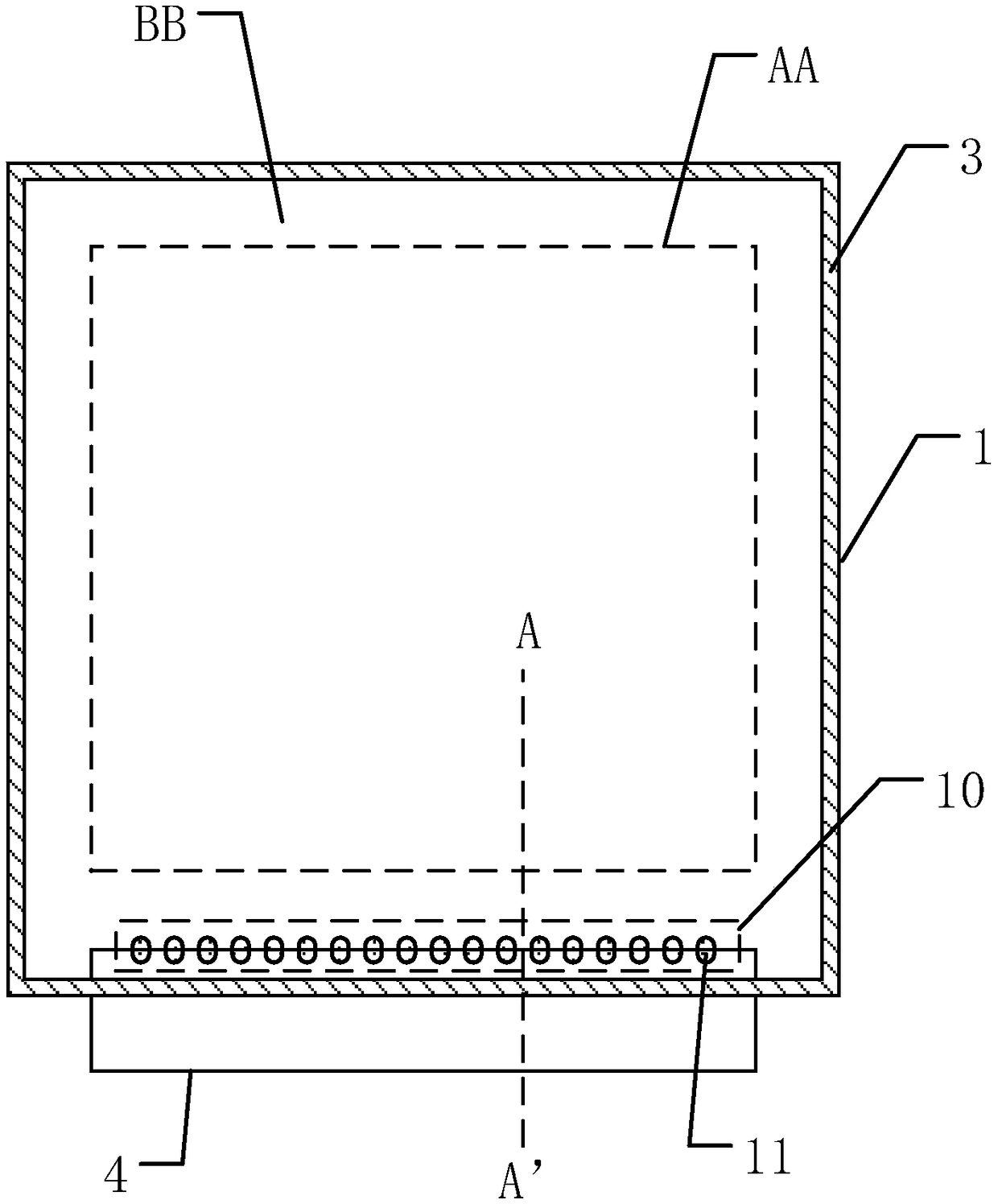
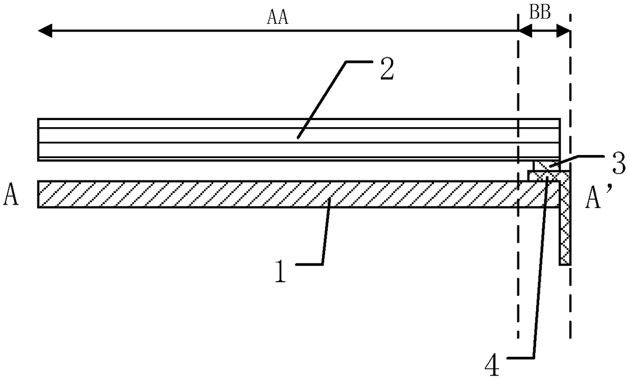
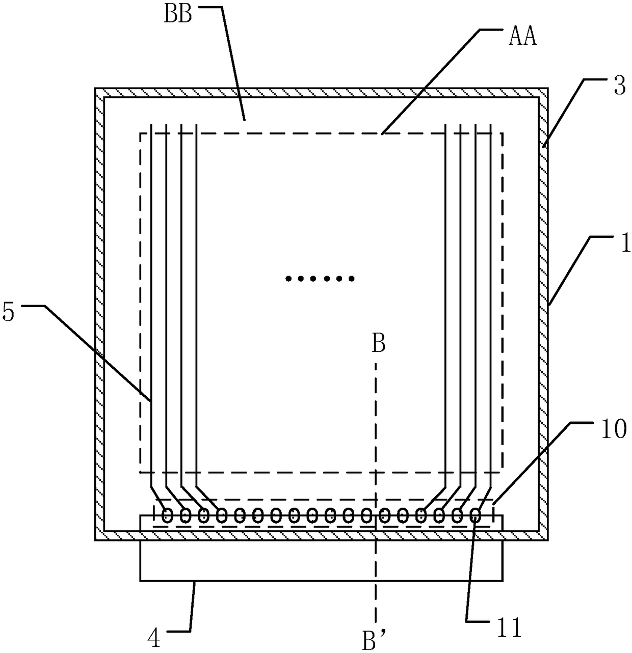
[0003] Although in order to improve the display quality, the peripheral circuits are also made as small as possible through various technologies in the prior art, but some functional devices, such as flexible circuit boards (FPC) and frame adhesives used to connect with external circuits, are still not fully integrated. Elimination, resulting in a relatively wide border of the display panel, so when the display panel is used to make a spliced ​​display device, the non-display area between the display areas of adjacent display panels will be wider, making the spliced ​​display device wider The splicing seams, and these wide splicing seams destroy the continuity of the entire image displayed by the splicing display device, which in turn affects the display and viewing effect

Method used


Image

  • Display panel, manufacturing method thereof, display device and splicing screen
  • Display panel, manufacturing method thereof, display device and splicing screen
  • Display panel, manufacturing method thereof, display device and splicing screen

Examples


Embodiment Construction

[0034] Various exemplary embodiments of the present invention will now be described in detail with reference to the accompanying drawings. It should be noted that the relative arrangements of components and steps, numerical expressions and numerical values ​​set forth in these embodiments do not limit the scope of the present invention unless specifically stated otherwise.

[0035] The following description of at least one exemplary embodiment is merely illustrative in nature and in no way taken as limiting the invention, its application or uses.

[0036] Techniques, methods and devices known to those of ordinary skill in the relevant art may not be discussed in detail, but where appropriate, such techniques, methods and devices should be considered part of the description.

[0037] In all examples shown and discussed herein, any specific values ​​should be construed as exemplary only, and not as limitations. Therefore, other instances of the exemplary embodiment may have dif...


PUM

PropertyMeasurementUnit
depthaaaaaaaaaa

Abstract

The invention discloses a display panel, a manufacturing method thereof, a display device and a splicing screen. The display panel comprises an array substrate and a first substrate which are opposite, a display area and a non-display area, wherein the non-display area comprises frame glue and a FPCB (flexible printed circuit board), the frame glue is arranged around the display area, and the frame glue is clamped and arranged between the array substrate and the first substrate; the array substrate comprises a binding area, and a plurality of conductive bonding pads are included in the bindingarea; the FPCB comprises a plurality of pins electrically connected with the conductive bonding pads; the frame glue and the FPCB are overlapped in the direction perpendicular to the array substrate.The display device comprises the display panel; the splicing screen comprises a plurality of the display devices which are connected. The narrow frame can be achieved without affecting the display effect of the display panel, the display effect of the display panel is improved, and accordingly, the process can be simplified, the manufacturing difficulty is reduced, a splicing seam of the splicingscreen manufactured by the display panel can be narrower, and accordingly, the splicing effect is not affected.

Description

technical field [0001] The present invention relates to the field of display technology, and more specifically, to a display panel, a manufacturing method thereof, a display device and a splicing screen. Background technique [0002] With the rapid development of flat panel display technology, its size and application scenarios are constantly expanding, and various manufacturers have launched larger-sized display panels. Due to the limitation of the production process, when the size of the display panel cannot be made larger, a spliced ​​display device emerges as the times require. Because it has a large-scene display effect and can bring users an immersive visual experience, the splicing display device is widely used in various occasions such as advertisements, publicity, and exhibitions. [0003] Although in order to improve the display quality, the peripheral circuits are also made as small as possible through various technologies in the prior art, but some functional de...

Claims


Application Information

Patent Timeline
Patent Type & Authority Applications(China)
IPC IPC(8): G09F9/302G02F1/1345
CPCG02F1/1345G02F1/13452G09F9/302
Inventor 席克瑞孔祥建秦锋刘金娥李小和崔婷婷
Owner SHANGHAI AVIC OPTOELECTRONICS
Why Eureka
Try Eureka