Acoustic absorber, acoustic wall and method for design and production

A technology of sound absorption and absorber, which is applied in the direction of sound-emitting devices, instruments, sensors, etc., can solve the problem of difficult to predict the cost of active sound-absorbing walls, and achieve the effect of easy industrial manufacturing

Active Publication Date: 2018-11-09
UNIV PARIS SACLAY +2
View PDF9 Cites 9 Cited by
  • Summary
  • Abstract
  • Description
  • Claims
  • Application Information

AI Technical Summary

Problems solved by technology

[0015] Difficult to predict the cost of active acoustic walls in the case of noise compensation in large spaces such as theaters or traffic halls

Method used


Image

  • Acoustic absorber, acoustic wall and method for design and production
  • Acoustic absorber, acoustic wall and method for design and production
  • Acoustic absorber, acoustic wall and method for design and production

Examples


Embodiment Construction

[0122] ●Single absorber

[0123] Figure 1 to Figure 7 A first example of an embodiment of the present invention is shown. For other examples, only their differences from the first embodiment will be described.

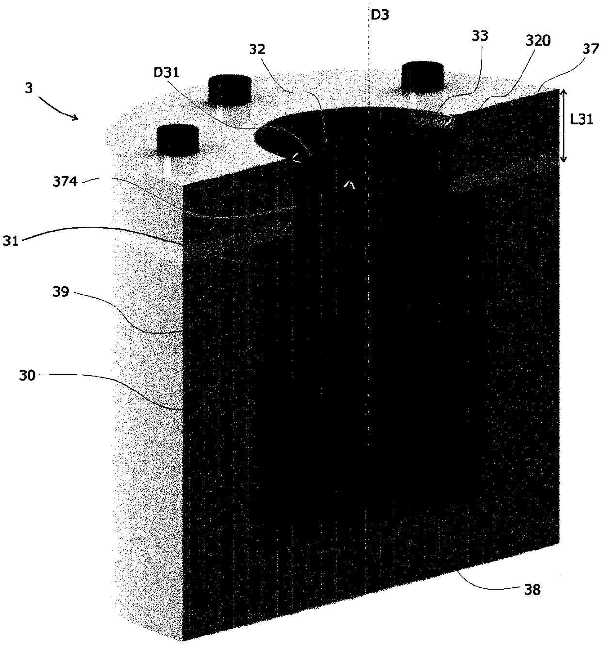
[0124] In a first example of this embodiment, an absorber 3 was fabricated and tested in the context of a study originally aimed at implementing an active noise reduction system with loudspeakers.

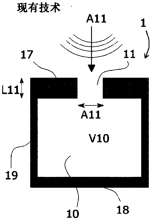
[0125] The absorber 3 has a cylindrical shape defining an inner cavity 30 . This cavity 30 is surrounded by a cylindrical wall 39 which is completely closed by a rear flat wall 38 and partly by a front wall 37 . The front wall 37 is pierced with a central hole opening towards the cylinder of the cavity 30 in the axial direction D3. The hole has a cylindrical shape passing through the thickness of the front wall 37 , forming a neck 31 of length L31 and having a cross section of A31 .

[0126] In the example described here, the wafer used is formed from a sil...


PUM


Abstract

The invention relates to a passive sound absorber (3, 4, 6, 7, 8) comprising a closed cavity (30, 80) opening to the outside via an inlet direction (D3) via a collar passing through the front wall inorder to form a Helmholtz resonator for a first frequency. According to the invention, said absorber further comprises at least one moving element, or membrane (32, 42, 62, 72a, 72b), suspended or held by suspensions (33, 43, 6140) in a position obstructing said collar in a non-sealed manner. The relative stiffness of the suspensions and of the membrane is determined such that the assembly resonates in a vibration following a "piston" movement at a second frequency different from the first frequency, producing an absorption for said second frequency or range of frequencies. A hybrid version comprises a coil (324) that is controlled to adjust the acoustic impedance of the absorber. The invention proposes an acoustic wall comprising a plurality of such absorbers produced by a repetitive structure opening through perforations, each receiving such a membrane, as well as a method for designing and producing such an absorber or wall.

Description

[0001] The invention relates to a passive sound absorber comprising a cavity open outwards in the direction of incidence of sound waves through a front wall via a neck so as to form a Helmholtz resonator of a first frequency. According to the invention, said absorber also comprises at least one moving element or wafer suspended or held in a position blocking said neck in a non-tight manner by a suspension. [0002] Additionally, the relative stiffness of the suspension and wafer is determined such that the assembly of the wafer and suspension arm vibrates in a "piston" type resonant mode at a second frequency different from the first frequency, thereby producing a response to the second frequency or range of frequencies. absorb. This second frequency lies between the first frequency and the third frequency, which is the frequency of the entire wafer with its suspension when measured in open air. [0003] In addition, hybrid types include coils that are controlled to adjust the ...

Claims


Application Information

Patent Timeline
Patent Type & Authority Applications(China)
IPC IPC(8): G10K11/16E04B1/84
CPCG10K11/16E04B2001/8485E04B1/86E04B1/8209E04B2001/8428H04R1/2896H04R9/06
Inventor 埃米尔·马丁奇科亚历山大·乌杜安斯特凡娜·杜兰德努迪尼·雅库比埃利·勒弗夫尔伊夫·奥勒冈
Owner UNIV PARIS SACLAY
Why Eureka
Try Eureka