Intelligent mower based on laser scanning radar sensor and control method of intelligent mower

A technology of laser scanning radar and lawn mower, which is applied to the chassis of harvesters, cutters, and agricultural implements, etc. Problems such as mowing height can achieve fast real-time response ability, accurate trimming of lawn height, and improvement of reliability and safety.

Active Publication Date: 2018-11-13
CHANGAN UNIV
View PDF6 Cites 26 Cited by
  • Summary
  • Abstract
  • Description
  • Claims
  • Application Information

AI Technical Summary

Problems solved by technology

[0002] Most of the existing lawn mowers are manual, and the height of the lawn trimmed is uneven, and it is time-consuming and labor-intensive
At present, most of the existing intelligent lawn mowers on the market are ultrasonic guidance. Although ultrasonic guidance can also identify obstacles ahead, it cannot accurately distinguish the height of the grass to be mowed, nor can it adjust the trimming height according to user needs. At the same time, ultrasonic guidance cannot Accurately grasping the overall lawn specifications cannot meet today's market demand
In addition, the existing smart lawn mowers do not control the mowing quality, but focus more on path planning and obstacle recognition. The mowing quality of the smart lawn mower will be affected by the driving speed, cutting speed Due to the influence of factors such as mowing depth and mowing depth, the driving speed of the existing intelligent lawn mower cannot be adjusted according to the height of the lawn. Drag, which affects the speed stability of the mower, especially on highly complex lawns
Existing intelligent lawn mowers do not adjust any driving speed and cutting speed for this phenomenon, resulting in low mowing quality

Method used


Image

  • Intelligent mower based on laser scanning radar sensor and control method of intelligent mower
  • Intelligent mower based on laser scanning radar sensor and control method of intelligent mower
  • Intelligent mower based on laser scanning radar sensor and control method of intelligent mower

Examples


Embodiment Construction

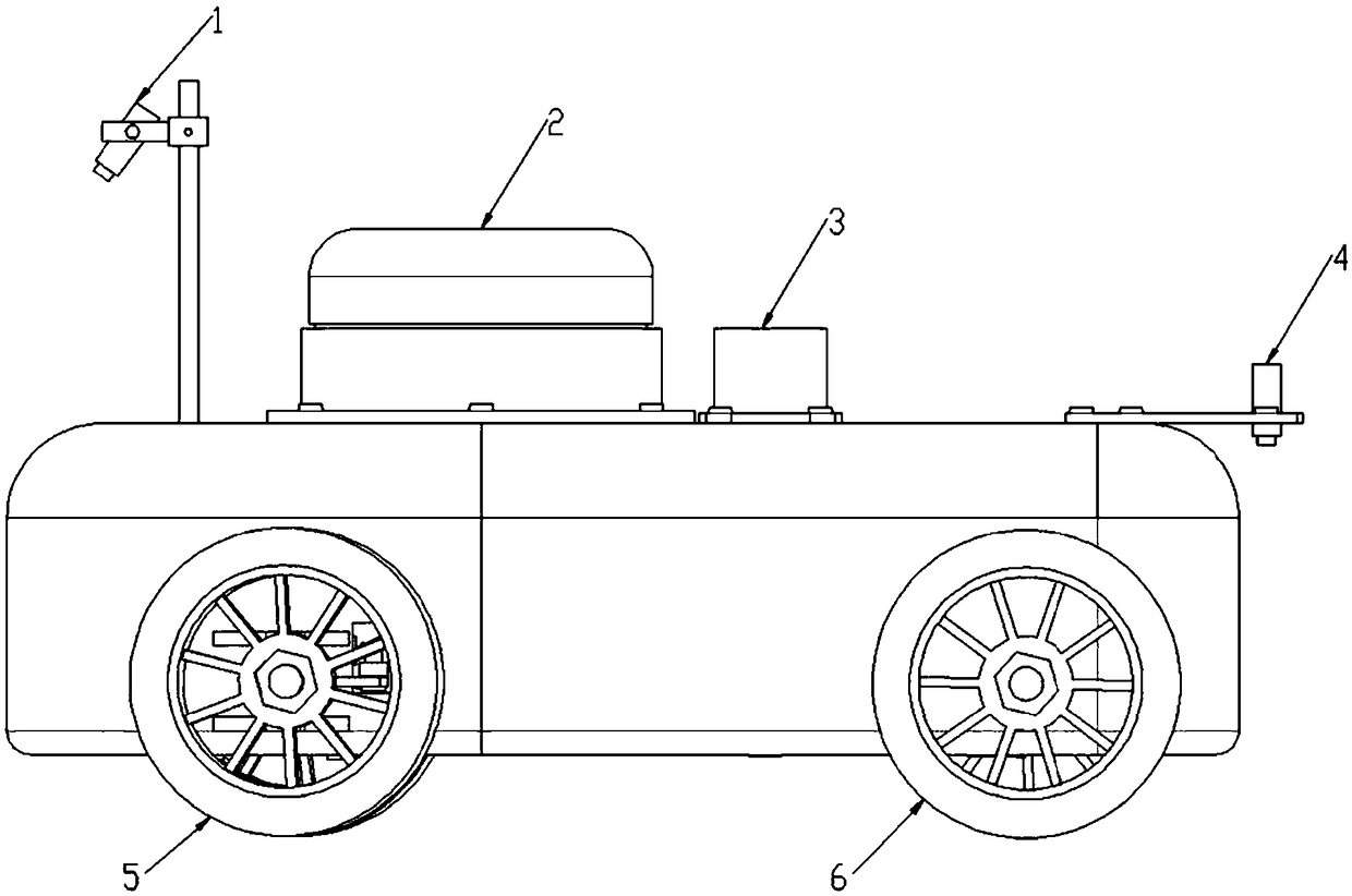
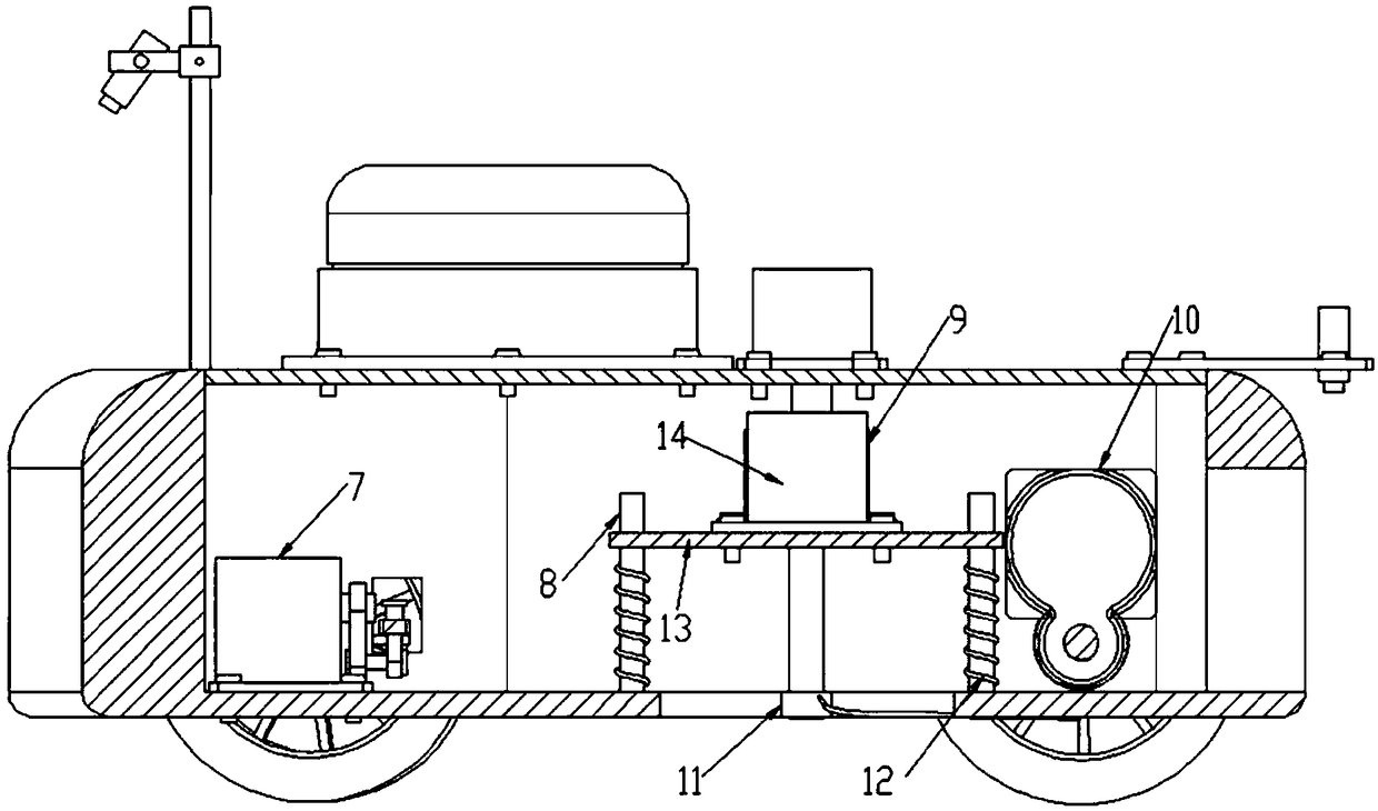
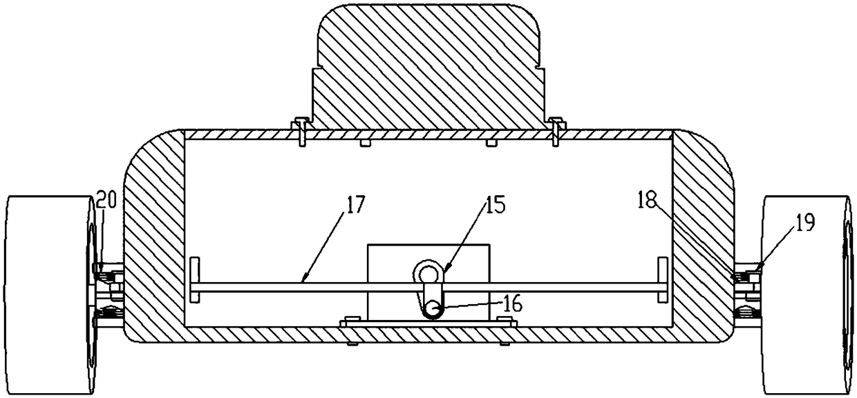
[0042] The present invention will be described in further detail below in conjunction with the accompanying drawings and specific embodiments.

[0043] refer to Figure 1 to Figure 3 , an intelligent lawn mower based on a laser scanning radar sensor of the present invention includes: a movable car body, an image acquisition device, a steering mechanism, a driving mechanism, a laser scanning radar sensor 2, a controller, a cutting motor 9 and a height adjustment mechanism .

[0044] The movable car body is used to support and fix the various parts of the intelligent lawn mower; through various sensors to achieve more accurate detection of the external environment, the image acquisition device is set on the movable car body to collect image information of the lawn; laser scanning The radar sensor 2 is arranged on the movable car body for collecting the information of the lawn around the intelligent lawn mower; the steering mechanism is arranged on the movable car body for the s...


PUM


Abstract

The invention discloses an intelligent mower based on a laser scanning radar sensor and a control method of the intelligent mower. The intelligent mower comprises a mobile cart body, an image collection device, a steering mechanism, a driving mechanism, the laser scanning radar sensor, a controller, a cutting motor and a height adjustment mechanism; a cutting line is installed on an output shaft of the cutting motor through a transmission device; the height adjustment mechanism is arranged on the mobile cart body, and the cutting motor is arranged on the height adjustment mechanism; the signaloutput end of the image collection device and the signal output end of the laser scanning radar sensor are connected with the signal input end of the controller separately, and the signal output endof the controller is connected with the steering mechanism, the driving mechanism, the cutting motor and the height adjustment mechanism separately. According to the intelligent mower, the height of ato-be-cut lawn can be precisely distinguished through the laser scanning radar sensor, the mowing height can be adjusted according to demands, and the intelligent mower has high mowing quality.

Description

technical field [0001] The invention belongs to the technical field of intelligent lawnmowers, in particular to an intelligent lawnmower based on a laser scanning radar sensor and a control method thereof. Background technique [0002] Most of the existing lawn mowers are manual, and the height of the trimmed lawns is uneven, and it is time-consuming and labor-intensive. At present, most of the existing intelligent lawn mowers on the market are ultrasonic guidance. Although ultrasonic guidance can also identify obstacles ahead, it cannot accurately distinguish the height of the grass to be mowed, nor can it adjust the trimming height according to user needs. At the same time, ultrasonic guidance cannot Accurately grasping the overall lawn specifications cannot meet the needs of today's market. In addition, the existing smart lawn mowers do not control the mowing quality, but focus more on path planning and obstacle recognition. The mowing quality of the smart lawn mower wil...

Claims


Application Information

Patent Timeline
Patent Type & Authority Applications(China)
IPC IPC(8): A01D34/00A01D34/416A01D67/00
CPCA01D34/008A01D34/416A01D67/00
Inventor 韩毅李昌乐董小明宋明洋
Owner CHANGAN UNIV
Why Eureka
Try Eureka