Multi-axis movement calculus discharging bed
A technology of multi-axis movement and stone bed removal, which is applied in the field of medical equipment, can solve the problems of expensive equipment, and achieve the effect of good stone removal effect, strong practicability and low cost
- Summary
- Abstract
- Description
- Claims
- Application Information
AI Technical Summary
Problems solved by technology
Method used
Image
Examples
Embodiment 1
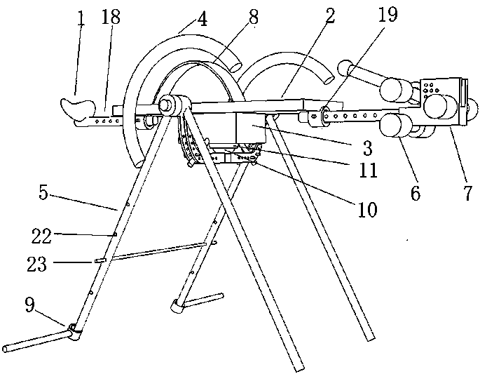
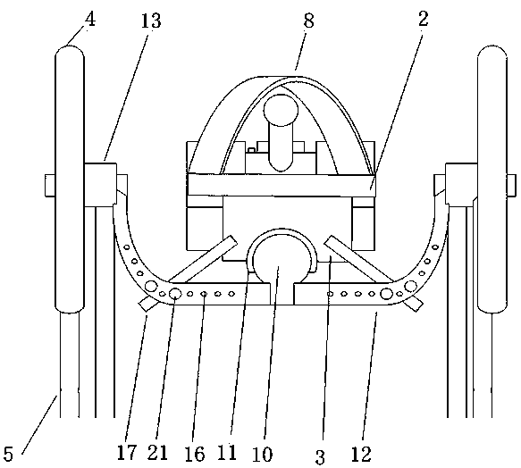
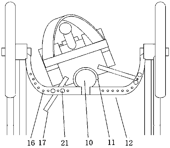
[0034] Such as Figure 1-3 As shown, the multi-axis motion stone removal bed in this embodiment includes: a backboard 2, a vibration device 3, a motion mechanism and a bed frame 5, and the vibration device 3 and the motion mechanism are installed on the backboard 2, and the motion mechanism includes a pitching mechanism and a rollover mechanism. mechanism, the kinematic mechanism is connected to the bed frame 5, and the bed frame 5 is used to support the kinematic mechanism and the backboard 2 for multi-axis motion.
[0035] The pitch mechanism includes a first rotating member 13 and a first bracket 12, and the first rotating member 13 is a ball bearing. The first bracket 12 is a U-shaped bracket that can rotate along the axis of rotation of the roller bearing. The depth of the U-shaped depression makes the plane of the backboard 2 substantially on the same plane as the axis of the pitch rotation. Both ends of the backboard 2 are connected with a length-adjusting bushing 19,...
Embodiment 2
[0050] Such as Figure 6 As shown, this embodiment is similar to Embodiment 1, the difference is that the rollover mechanism does not use a ball joint, but uses a second bracket 14 and a second rotating member 15 . In the center of the first bracket 12 is installed a second rotating member 15 vertically and fixedly connected thereto, which is a roller bearing. The second bracket 14 passes through the second rotating member 14 and is perpendicular to the axis of the first bracket 12 . The second support 14 extends to both ends, and is connected with a length adjusting shaft sleeve 19, and the inside is pierced with a length adjusting shaft 18, which is respectively connected to the headrest 1 and the ankle brace 7.
[0051] Such as Figure 7 and Figure 8 As shown, the rollover angle is controlled by the rollover adjustment rod 17 fixed on the vibration device 3 and inserted into the pitch rotation axis. The first bracket 12 has a hollow limit slot, which restricts the pitch...
Embodiment 3
[0054] Such as Figure 9 As shown, this embodiment is similar to the second embodiment, the difference is that the rollover angle is controlled by the servo motor 26 . A second gear 29 is installed on the second bracket 14 . The servo motor 26 is mounted on the first bracket 12 and is power-connected with the first gear 28 through a reducer 27 . The first gear 28 meshes with the second gear 29 to drive the second bracket 14 to rotate along the axis in the second rotating member 15 .
[0055] The second bracket 14 is fixedly connected with the vibrating device 3 or the backboard 2 through the fixed bracket, and rotates together with it. The fixed bracket can also play a position-limiting role, limiting the second bracket 14 from sliding back and forth in a large range in the shaft sleeve.
[0056] Other operation steps of this embodiment are the same as those of Embodiment 1.
PUM
 Abstract
Description
Claims
Application Information
 - R&D
- Intellectual Property
- Life Sciences
- Materials
- Tech Scout
- Unparalleled Data Quality
- Higher Quality Content
- 60% Fewer Hallucinations
Browse by: Latest US Patents, China's latest patents, Technical Efficacy Thesaurus, Application Domain, Technology Topic, Popular Technical Reports.
© 2025 PatSnap. All rights reserved.Legal|Privacy policy|Modern Slavery Act Transparency Statement|Sitemap|About US| Contact US: help@patsnap.com


