Catalyst used for removing dioxins and NO<x> in flue gas, and preparation method and applications thereof

A catalyst and flue gas technology, applied in chemical instruments and methods, physical/chemical process catalysts, metal/metal oxide/metal hydroxide catalysts, etc., can solve problems such as ineffective coordination and removal

Active Publication Date: 2018-11-13
UNIV OF SHANGHAI FOR SCI & TECH
View PDF17 Cites 8 Cited by
  • Summary
  • Abstract
  • Description
  • Claims
  • Application Information

AI Technical Summary

Problems solved by technology

[0006] Aiming at the above-mentioned technical problems in the prior art, the present invention provides a method for removing dioxin and NO in flue gas x Catalyst and preparation method and application, described this removes dioxin and NO in flue gas x Catalysts, preparation methods and applications to solve the inability to effectively coordinate the removal of dioxin and NO in the incineration flue gas in the prior art x technical issues

Method used


Image

  • Catalyst used for removing dioxins and NO&lt;x&gt; in flue gas, and preparation method and applications thereof
  • Catalyst used for removing dioxins and NO&lt;x&gt; in flue gas, and preparation method and applications thereof

Examples


Embodiment 1

[0031] In the present invention, MnCeO is prepared by sol-gel method x / TiO 2 Composite catalyst, the preparation process is as follows: Take 34ml tetrabutyl titanate solution, 30ml absolute ethanol and 20ml glacial acetic acid according to the proportion and stir at room temperature until they are evenly mixed to form solution A; take 3ml manganese nitrate, 4.3g cerium nitrate, Absolute ethanol and 5-10ml deionized water are stirred at room temperature until they are evenly mixed to form solution B; drop solution B into solution A under vigorous stirring to form solution C; keep stirring solution C until the solution turns transparent Then put the sol at room temperature for 24 hours to form a gel, then place the gel in an oven at 105°C for 8 hours and then place it in a muffle furnace for calcination; the muffle furnace rises from room temperature at a rate of 10°C / min Stay at 300°C for 30 minutes, continue to raise the temperature to 550°C and stay for 3 hours, then cool d...

Embodiment 2

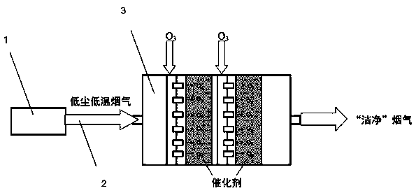
[0033] Such as figure 1 As shown, the low-dust and low-temperature flue gas after dedusting by the dedusting device 1 is input from the pipeline 2 into a MnCeO x / TiO 2 In the device 3 of composite catalyst; Ozone is sprayed into MnCeO through special-purpose pipeline (this pipeline contains some injection apertures) x / TiO 2 Inside the composite catalyst, the two are fully mixed (5min) to achieve ozone and MnCeO x / TiO 2 Composite catalyst coupling; flue gas passing through ozone and MnCeO x / TiO 2 In the pre-coupled device of the composite catalyst (the residence time of the flue gas flow on the surface of the catalyst is 1s; the total residence time of the flue gas flow in the catalytic device is less than 5s), remove dioxin and NO x The final "clean" flue gas is exhausted.

[0034] In the above flue gas, NO / NH 3 The molar ratio of = 0.8-1, the initial concentration of NO is 300-1000ppm, the initial concentration of dioxin is 2.0-12.6ng I-TEQ / m 3 .

[0035] Furthe...


PUM

PropertyMeasurementUnit
specific surface areaaaaaaaaaaa
particle size (mesh)aaaaaaaaaa
specific surface areaaaaaaaaaaa

Abstract

The invention provides a catalyst used for removing dioxins and NO<x> in flue gas. TiO2 is taken as a carrier, an active component is dispersed on the surface of the carrier; the active component is composed of MnO<x> and CeO2. The invention also provides a preparation method of the catalyst used for removing dioxins and NO<x> in flue gas, and a method used for removing dioxins and NO<x> in flue gas with the catalyst. According to the method, flue gas is subjected to dust removing using a dust removing device, is conveyed into a device containing the catalyst through a pipeline, ozone is sprayed into the device through another pipeline provided with a plurality of small spray holes, flue gas, ozone, and the catalyst are mixed fully in the device, and after removing of dioxins and NO<x>, the flue gas is discharged. According to the method, ozone and the manganese containing catalyst are combined for cooperative removing of dioxins and NO<x>.

Description

technical field [0001] The invention belongs to the field of chemical industry and relates to a method for treating flue gas, specifically a method for removing dioxin and NO in flue gas. x Catalysts and preparation methods and applications. Background technique [0002] Dioxins and nitrogen oxides (NO x ) Emission control is two major issues that have attracted much attention in the field of environmental protection and need to be solved urgently. In recent years, incineration has developed rapidly in my country because it can effectively realize the "reduction, harmlessness, and recycling" of garbage. Although it has alleviated the pressure of "garbage siege" in my country to a certain extent, the problem caused by insufficient combustion The secondary pollution caused by dioxin has become the focus of attention from all walks of life. The Ministry of Environmental Protection of my country recently promulgated the "Life Waste Incinerator Pollution Discharge Standard GB18...

Claims


Application Information

Patent Timeline
Patent Type & Authority Applications(China)
IPC IPC(8): B01J23/34B01D53/90B01D53/86B01D53/70B01D53/56
CPCB01D53/8628B01D53/8662B01D53/90B01D2255/2065B01D2255/20707B01D2255/2073B01J23/34
Inventor 王秋麟周健健金晶张建超林丰
Owner UNIV OF SHANGHAI FOR SCI & TECH
Why Eureka
Try Eureka