
Paint spraying device for production surface of chemical engineering material

A technology for chemical and paint spraying guns, which is applied to the device for coating liquid on the surface, the spraying device, the liquid spraying device, etc., can solve the problems of contamination with dust, waste, paint can not be dried in time, affecting the overall effect of chemical materials, etc. The effect of spray paint drying quickly and preventing dust contamination

Inactive Publication Date: 2018-11-13
ANHUI ORIGINAL POWER PRODUCTIVITY PROMOTION CENT CO LTD
View PDF0 Cites 0 Cited by
  • Summary
  • Abstract
  • Description
  • Claims
  • Application Information

AI Technical Summary

Problems solved by technology

[0002] Most chemical materials need to spray paint on the surface during production. The paint is atomized into fine paint droplets through compressed air, and sprayed onto the surface of the object under the drive of the air flow. At the same time, an air pressure device needs to be connected to the outside. In comparison, it is more time-sensitive, the spraying effect is more beautiful, and the efficiency is 5 to 10 times higher than that of brushing. However, the existing technology has the following problems: in the case of cold weather, the paint cannot be dried in time after spraying, and contamination will occur. Dust and waste will affect the overall effect of chemical materials

Method used


Image

  • Paint spraying device for production surface of chemical engineering material
  • Paint spraying device for production surface of chemical engineering material
  • Paint spraying device for production surface of chemical engineering material

Examples


Embodiment

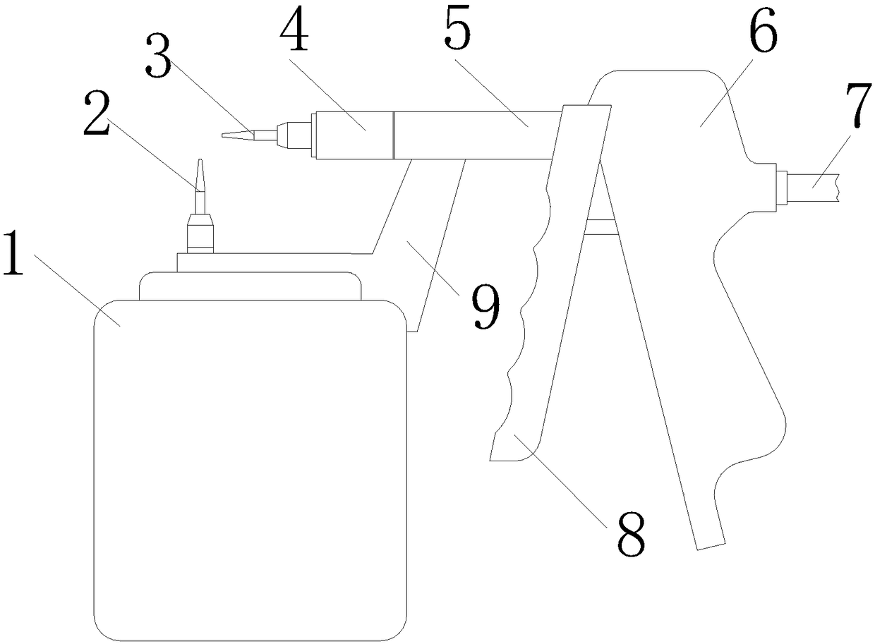
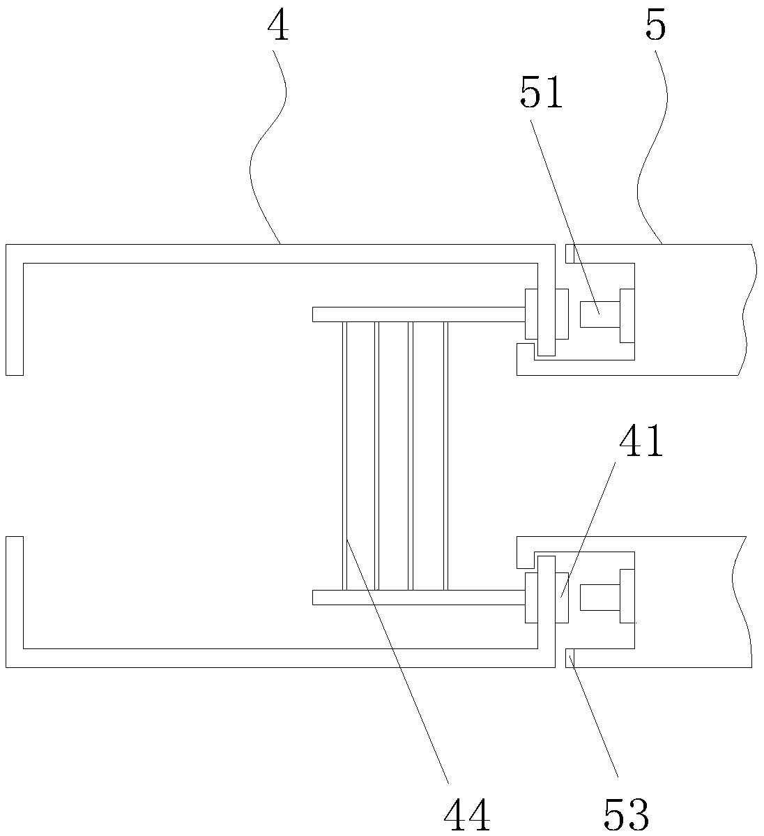
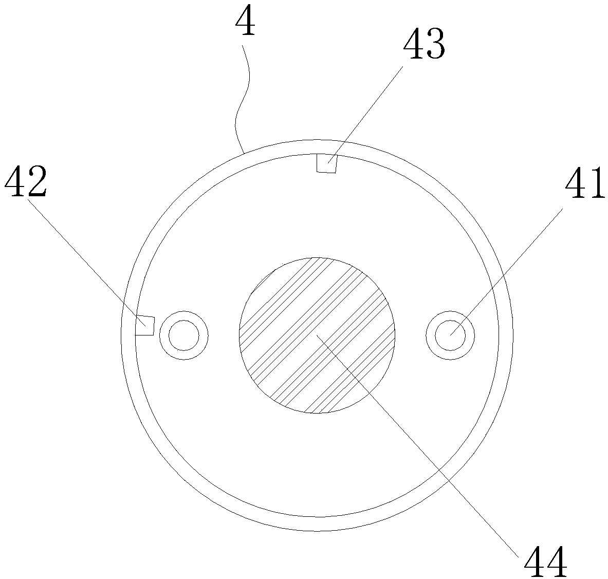
[0020] see Figure 1-4 , the present invention provides the following technical solutions: a surface painting device for producing chemical materials, comprising a paint bucket 1, a paint spray gun body 6, a handle 8 is provided on one side of the paint spray gun body 6, and the other side of the paint spray gun body 6 away from the handle 8 An air pressure input terminal 7 is provided, and a spray barrel 5 is integrally formed on the side close to the handle 8 at the upper end of the paint spray gun body 6, and the other end of the spray barrel 5 away from the paint spray gun body 6 is rotatably connected with a heater device 4, and the spray barrel 5 is connected to the heater The end connected to the device 4 is provided with two metal caps 51, and the inner wall of the end of the spray tube 5 connected to the heater device 4 is provided with a limit strip 52, and the other end of the heater device 4 away from the spray tube 5 is provided with a second nozzle. 3;

[0021] ...


PUM


Abstract

The invention discloses a paint spraying device for a production surface of a chemical engineering material. The device comprises a coating barrel and a paint spraying gun body, a handle is arranged on one side of the paint spraying gun body, the other side of the paint spraying gun body is provided with an air pressure input end, a spraying cylinder is arranged on one side, close to the handle, of the upper end of the paint spraying gun body, away from the paint spraying gun body, of the spraying cylinder is provided with a heater device, two metal caps are arranged at one end, connected withthe heater device, of the spraying cylinder, two metal sheets are arranged at one end, connected with the spray cylinder, of the heater device, an electric heating wire mesh is arranged inside the heater device, heating and cooling of the electric heating wire mesh are controlled through rotation of the heater device, after the paint spraying is completed, the electric heating wire mesh is heatedby rotating the heater device to turn on the circuit, gas is input from the air pressure input end and then is heated through the electric heating wire screen, and the temperature of the sprayed gasrises, so that the purpose of fast drying the paint on the surface of the chemical material is achieved, and dust can be prevented from being contaminated due to the fact that the paint cannot be dried when the weather is cold.

Description

technical field [0001] The invention belongs to the technical field of surface painting devices for chemical materials, and in particular relates to a surface painting device for producing chemical materials. Background technique [0002] Most chemical materials need to spray paint on the surface during production. The paint is atomized into fine paint droplets through compressed air, and sprayed onto the surface of the object under the drive of the airflow. At the same time, an air pressure device needs to be connected to the outside. In comparison, it is more time-sensitive, the spraying effect is more beautiful, and the efficiency is 5 to 10 times higher than that of brushing. However, the existing technology has the following problems: in the case of cold weather, the paint cannot be dried in time after spraying, and contamination will occur. Dust and waste will affect the overall effect of chemical materials. Contents of the invention [0003] In order to solve the p...

Claims


Application Information

Patent Timeline
IPC IPC(8): B05B9/01B05D3/04
CPCB05B9/01B05D3/0413
Inventor 徐忠汤勇花
Owner ANHUI ORIGINAL POWER PRODUCTIVITY PROMOTION CENT CO LTD
Learn More