Tube cleaning assembly and tube cleaning method

A technology for cleaning components and pipelines, applied in the directions of cleaning methods and utensils, cleaning hollow objects, chemical instruments and methods, etc., can solve problems such as affecting production capacity, and achieve the effect of improving running time, not easy to condense, and reducing production capacity loss

Inactive Publication Date: 2018-11-13
WUHAN CHINA STAR OPTOELECTRONICS SEMICON DISPLAY TECH CO LTD
View PDF5 Cites 0 Cited by
  • Summary
  • Abstract
  • Description
  • Claims
  • Application Information

AI Technical Summary

Problems solved by technology

However, this technology requires equipment to be shut down for a long time, which will seriously affect production capacity

Method used


Image

  • Tube cleaning assembly and tube cleaning method
  • Tube cleaning assembly and tube cleaning method

Examples


Embodiment Construction

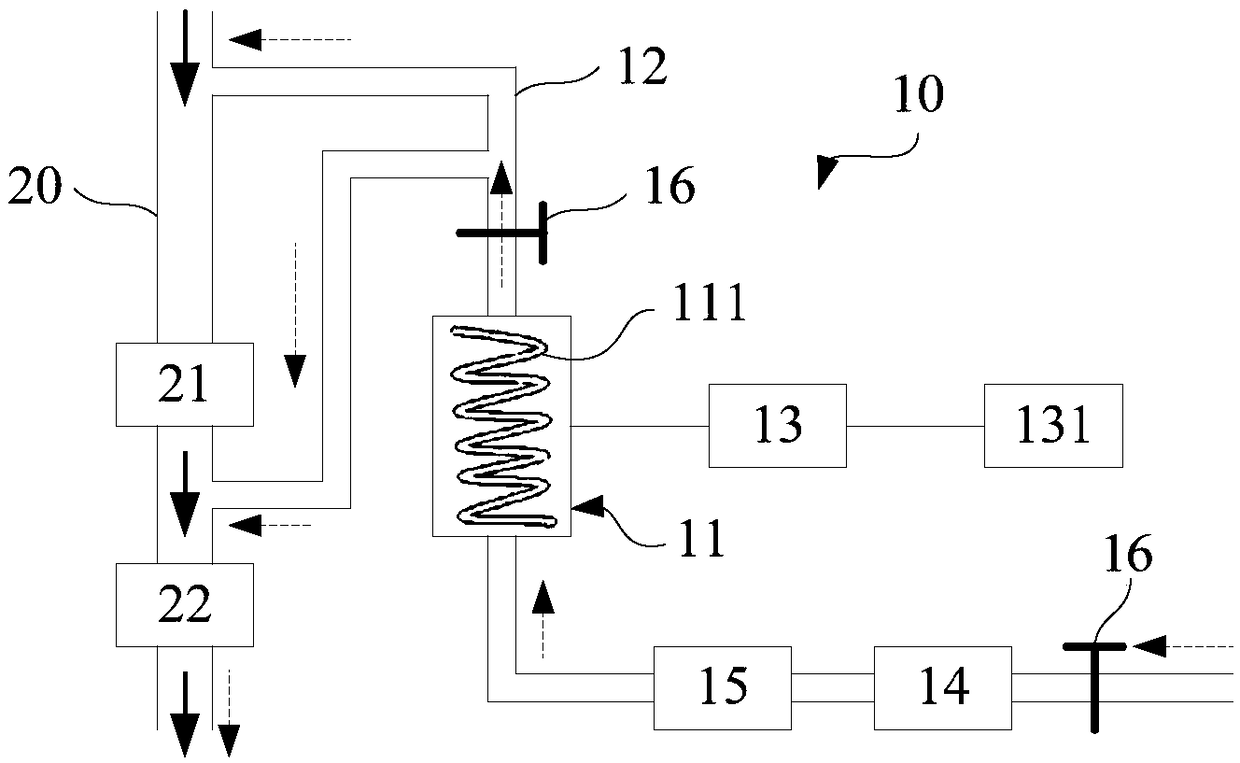
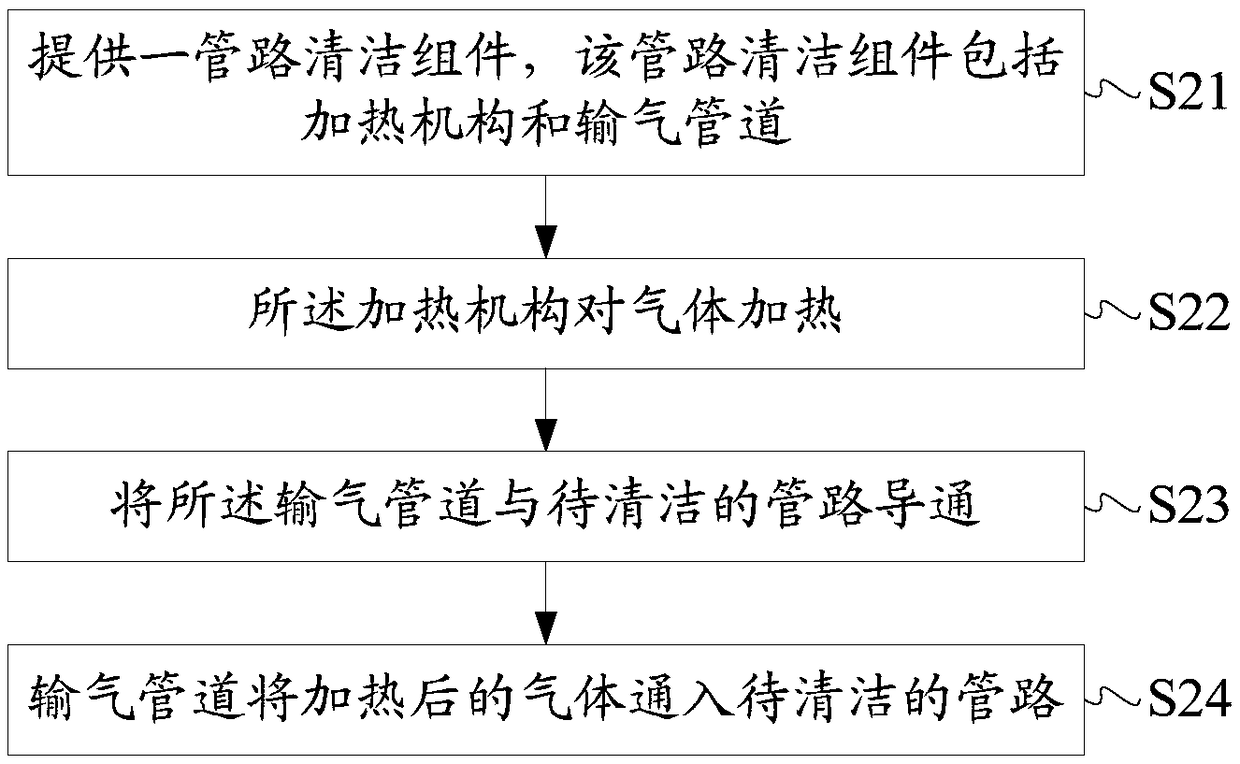
[0013] The main purpose of this application is to design a pipeline cleaning assembly including a heating mechanism and a gas delivery pipeline, the heating mechanism heats the gas, the gas delivery pipeline is connected to the pipeline to be cleaned to pass the heated gas into the pipeline, and the gas conducts heat to the pipeline. Dust pollutants make it difficult for dust pollutants to condense, which is beneficial to prevent blockage in the pipeline. During the entire cleaning process, since there is no need to disassemble the pipeline for maintenance, it is beneficial to improve equipment running time and reduce production loss. .

[0014] The pipeline cleaning assembly of the present application can be applied to manufacturing equipment containing special gas processes in the field of display device manufacturing, such as chemical vapor deposition machines, dry etching machines, and flexible packaging machines. Wherein, the gas introduced into the special gas manufactur...


PUM


Abstract

The application discloses a tube cleaning assembly and a tube cleaning method. The tube cleaning assembly comprises a heating mechanism and a gas transportation tube, wherein the heating mechanism isused for heating gas; and the gas transportation tube is communicated with a tube to be cleaned and introducing heated gas into the tube. Based on this, the tube cleaning assembly disclosed by the invention facilitates prolonging the running time of the tube and reducing the loss of the production capacity while cleaning the tube.

Description

technical field [0001] The present application relates to the field of display technology, in particular to the field of cleaning of display device manufacturing equipment, and in particular to a pipeline cleaning component and a pipeline cleaning method. Background technique [0002] During the manufacturing process of the display device, various manufacturing equipment will generate a large amount of dust pollutants. These pollutants that cannot be discharged will adhere to the side wall of the pipeline after cooling, which will not only cause insufficient negative pressure or blockage of the pipeline, It is easy to cause equipment downtime and affect the normal operation of the equipment, and the pollutants will corrode the sealing ring, accelerate its aging, and increase the risk of gas leakage in the pipeline. In order to solve this problem, in the prior art, the equipment is generally shut down, and the pipeline is regularly disassembled to maintain the pipeline. Howe...

Claims


Application Information

Patent Timeline
Patent Type & Authority Applications(China)
IPC IPC(8): B08B9/027
CPCB08B9/027
Inventor 刘干
Owner WUHAN CHINA STAR OPTOELECTRONICS SEMICON DISPLAY TECH CO LTD
Why Eureka
Try Eureka