
Product mold stamping machine

A stamping machine and mold technology, which is applied in the field of product mold stamping machines, can solve the problems of large volume, high cost, low stamping accuracy, etc., and achieve the effects of reducing labor intensity, low manufacturing cost and maintenance cost, and improving work efficiency

Inactive Publication Date: 2018-11-13
CIXI LANGHUA MACHINERY TECH CO LTD
View PDF0 Cites 0 Cited by
  • Summary
  • Abstract
  • Description
  • Claims
  • Application Information

AI Technical Summary

Problems solved by technology

The precision requirements of high-tech products are generally high. Therefore, in order to ensure product quality, molds must have high precision. Existing mold stamping machines have problems of high cost, large volume, and low stamping accuracy, which cannot meet the needs of enterprises, especially High-Tech Companies

Method used


Image

  • Product mold stamping machine
  • Product mold stamping machine
  • Product mold stamping machine

Examples


Embodiment Construction

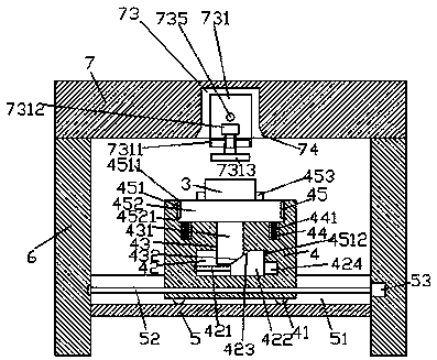
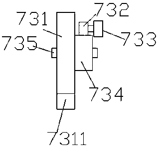
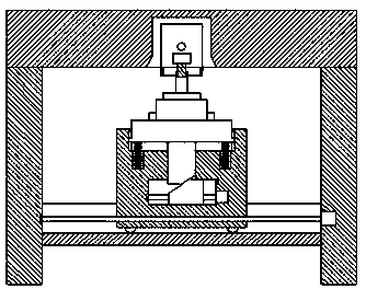
[0023] Such as Figure 1-Figure 6 As shown, a product mold stamping device of the present invention includes a top beam 7 and pillars 6 fixed on the bottom of both sides of the top beam 7, and brackets 5 are fixed between the pillars 6 below the top beam 7 , the bracket 5 is provided with a first sliding groove 51, and the first sliding groove 51 is provided with a first screw rod 52 extending left and right, and the first screw rod 52 is screw-fitted and connected There is a sliding joint block 4, the upper part of the sliding joint block 4 is located outside the top of the bracket 5, the sliding joint block 4 is provided with a sliding joint cavity 42, and the top of the sliding joint block 4 is provided with a square groove 45. Between the middle part of the inner bottom of the square groove 45 and the middle part of the inner top of the sliding cavity 42, there is a communication groove 43 connecting the inside of the sliding block 4 up and down. Two screw-shaped rods 421...


PUM


Abstract

The invention discloses a product mold stamping machine. The product mold stamping machine comprises a top beam and supporting pillars fixed to the bottoms of the two sides of the top beam. A supporting frame is fixedly arranged between the supporting pillars under the top beam. A first sliding connecting groove is formed in the supporting frame. A first threaded rod extending left and right is arranged in the first sliding connecting groove. A sliding connecting block is connected with the first threaded rod in a threaded fit mode. The upper portion of the sliding connecting block is locatedoutside the top end of the supporting frame. A sliding connecting cavity is formed in the sliding connecting block. A square groove is formed in the top end of the sliding connecting block. A communicating groove vertically communicating with the inside of the sliding connecting block is formed between the middle of the bottom surface inside the square groove and the middle of the top end in the sliding connecting cavity. A second threaded rod extending left and right is arranged in the sliding connecting cavity. A squeezing inclined block is arranged on the second threaded rod, and a first inclined surface is arranged on the upper portion of the left side of the squeezing inclined block. The product mold stamping machine is simple in structure, low in manufacturing cost and maintaining cost, and capable of automatically controlling the lifting stamping work and automatic angle adjustment of a stamping head.

Description

technical field [0001] The invention relates to the technical field of die stamping, in particular to a product die stamper. Background technique [0002] In the high-tech industry, labor costs account for a large part. In order to make products competitive, it is urgent to reduce costs in the production of products. Therefore, it is inevitable to use molds to produce products in batches. The precision requirements of high-tech products are generally high. Therefore, in order to ensure product quality, molds must have high precision. Existing mold stamping machines have problems of high cost, large volume, and low stamping accuracy, which cannot meet the needs of enterprises, especially High-Tech Companies. Contents of the invention [0003] The technical problem to be solved by the present invention is to provide a product mold stamper, which can solve the above-mentioned problems in the prior art. [0004] The present invention is achieved through the following technic...

Claims


Application Information

Patent Timeline
IPC IPC(8): B21D37/10B21D37/04
CPCB21D37/10B21D37/04
Inventor 方余
Owner CIXI LANGHUA MACHINERY TECH CO LTD
Learn More