A laser marking machine

A laser marking machine and laser marking technology, applied in the field of laser marking machines, can solve problems such as high cost, low production efficiency, and slow marking speed, and achieve the effects of low cost, high production efficiency, and fast marking speed

Active Publication Date: 2021-02-05
HANS LASER TECH IND GRP CO LTD
View PDF7 Cites 0 Cited by
  • Summary
  • Abstract
  • Description
  • Claims
  • Application Information

AI Technical Summary

Problems solved by technology

[0003] The technical problem to be solved by the present invention is to provide a laser marking machine in view of the deficiencies of the prior art, which overcomes the slow marking speed and the cost of marking due to the inability of the existing devices to mark multiple products or multiple surfaces of products. The problem of high and low productivity

Method used


Image

  • A laser marking machine
  • A laser marking machine
  • A laser marking machine

Examples


Embodiment Construction

[0024] Now in conjunction with the accompanying drawings, the preferred embodiments of the present invention will be described in detail.

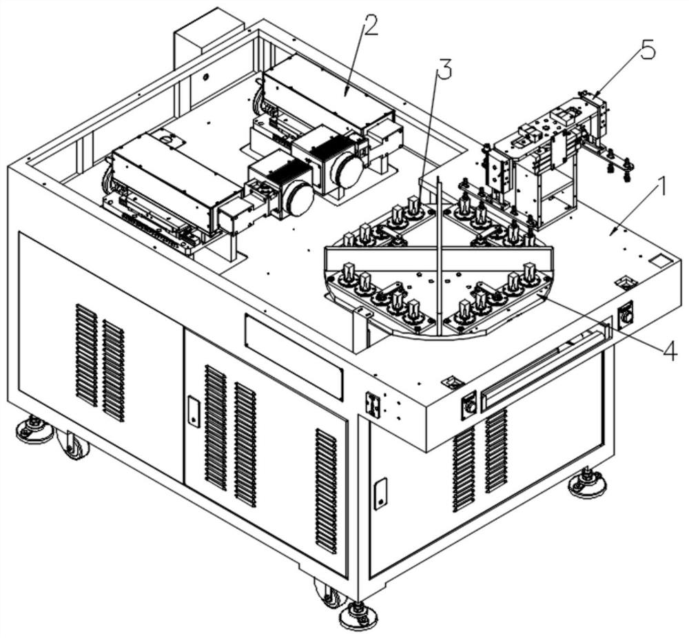
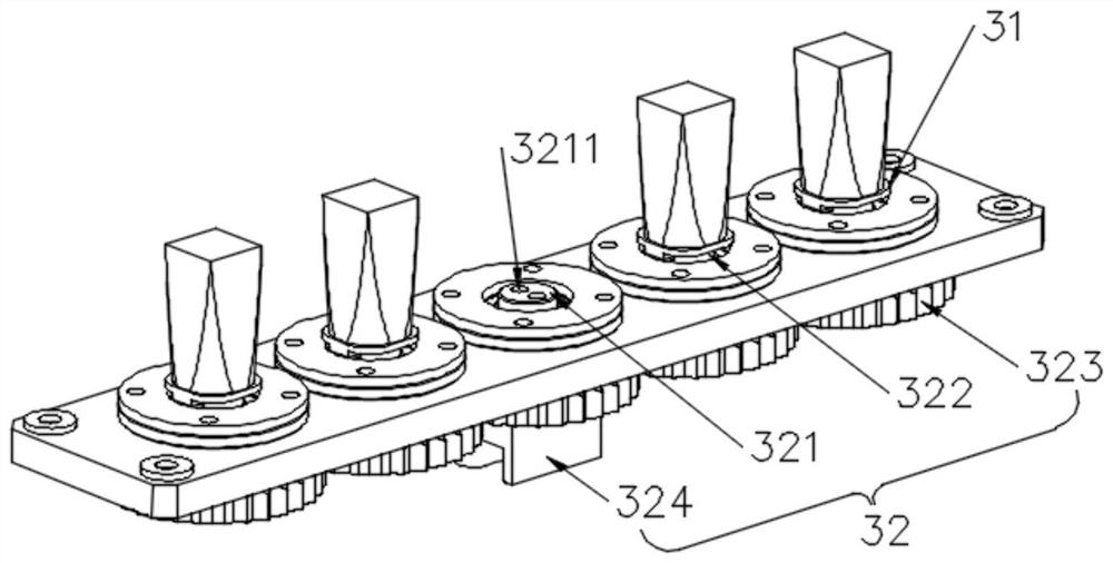
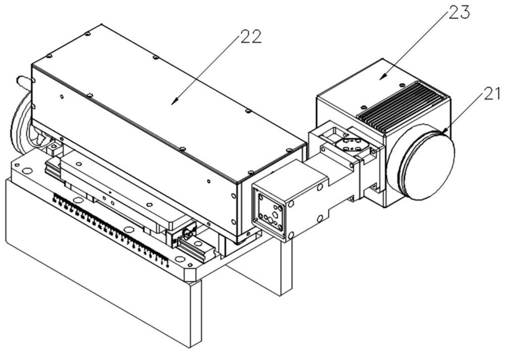
[0025] Such as figure 1 , 2 , 3, this embodiment provides a laser marking machine, the laser marking machine includes a cabinet 1, a laser marking device 2 and a laser marking fixture assembly 3 arranged on The marking fixture assembly 3 includes at least two fixtures 31 for fixing products, a transmission assembly 32 provided with a driving shaft 321 and a driven shaft 322 connected to the corresponding fixture 31, and the driving shaft 321 passes through the driven Driven by the shaft 322 , the jig 31 rotates synchronously; the laser marking device 2 includes a laser head 21 for marking products on the jig 31 . Wherein, the transmission assembly 32 includes a driven shaft 322 connected to the corresponding jig 31 and a driving shaft 321 that drives the driven shaft 322 to rotate. Preferably, the transmission assembly 32 is a gear tran...


PUM


Abstract

The invention relates to the field of laser marking, in particular to a laser marking machine. The laser marking machine includes a cabinet, a laser marking device installed on the cabinet, and a laser marking fixture assembly. The laser marking fixture assembly includes at least two fixtures for fixing products, and is provided with a driving shaft and connected to the corresponding fixture. The driving assembly of the driven shaft, the driving shaft drives the corresponding jig to rotate synchronously through the driven shaft; the laser marking device includes a laser head for marking the product on the jig. By arranging a laser marking jig assembly that can fix at least two products and make the products synchronously self-propelled on the rotary table, a laser head for marking the product on the jig is provided on the laser marking device, so that Realize laser marking on multiple products or multiple surfaces of products, with fast marking speed, low cost and high production efficiency.

Description

technical field [0001] The invention relates to the technical field of laser marking, in particular to a laser marking machine. Background technique [0002] At present, the demand for cosmetics in the market is increasing, and the production capacity of cosmetics manufacturers also needs to be increased accordingly. The devices used in traditional lipstick cap marking can generally only realize the rotary marking of a single product, or can only mark a few sides of the product at a time, so there are problems such as slow marking speed, high cost, and low production efficiency. Facing the growing market Demand, such devices can no longer meet the existing capacity demand. Contents of the invention [0003] The technical problem to be solved by the present invention is to provide a laser marking machine in view of the deficiencies of the prior art, which overcomes the slow marking speed and the cost of marking due to the inability of the existing devices to mark multiple ...

Claims


Application Information

Patent Timeline
Patent Type & Authority Patents(China)
IPC IPC(8): B23K26/362B23K26/70
CPCB23K26/361B23K26/702
Inventor 邓建斌吕启涛曹洪涛刘亮杨柯廖文胡述旭李金平刘康高云峰
Owner HANS LASER TECH IND GRP CO LTD
Why Eureka
Try Eureka