
A fast circle cutting method for CNC laser cutting machine

A CNC laser and cutting machine technology, applied in laser welding equipment, metal processing equipment, welding equipment, etc., can solve the problems that large flat plates cannot be placed horizontally, the processing efficiency of machine tools is reduced, and the cutting head is frequently raised and lowered, etc., to protect the human body Healthy, small mechanical vibration, and efficiency-enhancing effects

Active Publication Date: 2020-09-15
山东北易车业有限公司
View PDF8 Cites 0 Cited by
  • Summary
  • Abstract
  • Description
  • Claims
  • Application Information

AI Technical Summary

Problems solved by technology

If there are many graphics, the cutting head will frequently rise and fall
And due to the technological requirements of laser cutting, the cutting head can only be raised and lowered safely when the movement is stopped. Therefore, after each graphic is processed, the machine tool needs to be decelerated to zero, so that the cutting head can rise, and then accelerate to move to At the starting point of the next figure, the cutting head can only be lowered by decelerating to zero. Repeatedly, it is very time-consuming and labor-intensive, and the processing efficiency of the machine tool is reduced; at the same time, but in the process of laser cutting, the laser often cuts to the support. For the support frame of the flat plate, after the laser cutting machine has been used for a period of time, the surface of the support frame supporting the large flat plate will be cut, and the upper surface of the support frame will be uneven, sometimes making the large flat plate unable to be placed horizontally, thus affecting the accuracy of the workpiece , affecting the workpiece assembly

Method used


Image

  • A fast circle cutting method for CNC laser cutting machine
  • A fast circle cutting method for CNC laser cutting machine
  • A fast circle cutting method for CNC laser cutting machine

Examples


Embodiment Construction

[0033] use Figure 1 to Figure 8 A fast circle cutting method for a numerically controlled laser cutting machine of the present invention is described as follows.

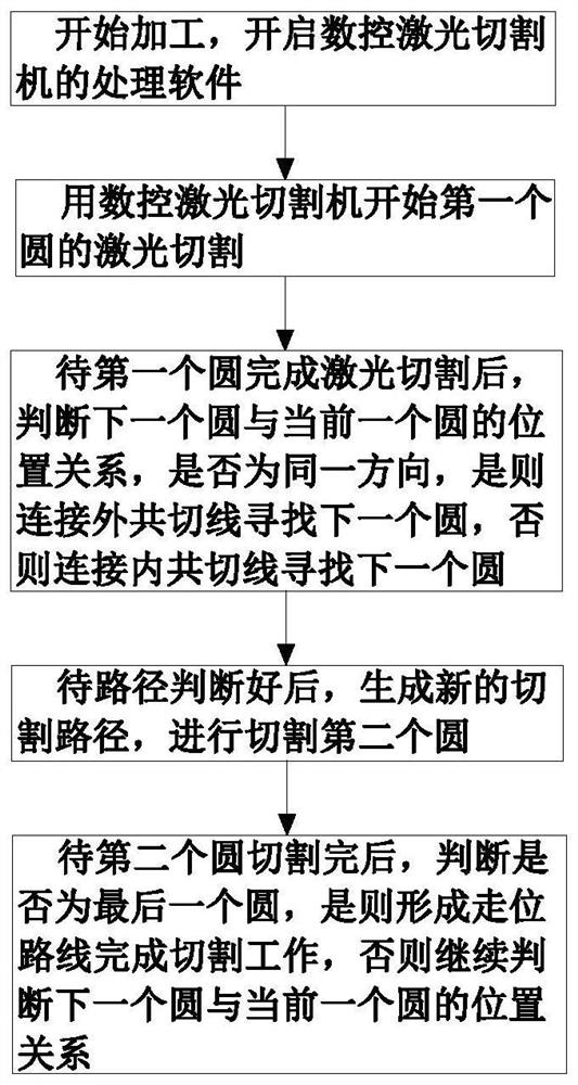
[0034] Such as Figure 1 to Figure 4 As shown, a kind of CNC laser cutting machine fast circle cutting method described in the present invention includes computer-controlled CNC laser cutting machine processing software for arc cutting, and the circle cutting method includes the following steps:

[0035] Step 1: Start processing and start the processing software of the CNC laser cutting machine;

[0036] Step 2: After the processing software is opened in step 1, start the laser cutting of the first circle with the CNC laser cutting machine; before the cutting circle of the laser head 4 reaches the corresponding circular path, the motor 11 drives the lead screw 12 to rotate, Make the slider 14 move on the lead screw 12, and move the slider 14 to the support guide rail 2 by controlling the motor one 11, and the dri...


PUM


Abstract

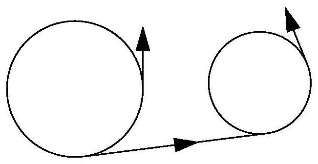
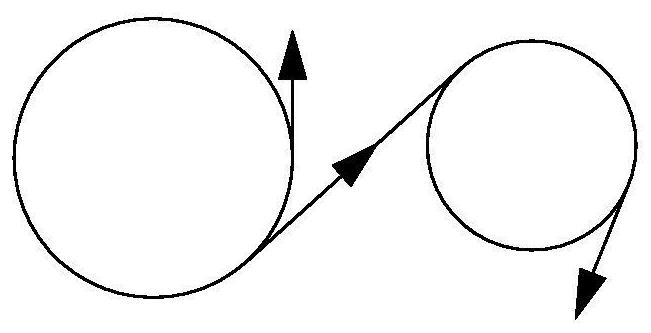
The invention belongs to the technical field of laser cutting and particularly relates to a fast circle cutting method of a numerical control laser cutting machine. The fast circle cutting method comprises the following steps: starting processing software of the numerical control laser cutting machine; adopting the numerical control laser cutting machine to start laser cutting of a first circle; after laser cutting of the first circle is finished, judging whether the position relationship between next circle and the current circle is the same direction or not, if yes, connecting external common tangent lines and searching next circle, otherwise, connecting internal common tangent lines and searching next circle; generating a new cutting path, and cutting a second circle; and after cuttingof the second circle is finished, judging whether the second circle is the last circle or not, if yes, forming a walking path and finishing cutting operation, otherwise, continuing to judge the position relationship between next circle and the current circle. With adoption of the fast circle cutting method, the circle cutting efficiency and precision of the numerical control laser cutting machineare improved, and the numerical control laser cutting machine is facilitated to cut the circle in a better and faster manner.

Description

technical field [0001] The invention belongs to the technical field of laser cutting, in particular to a method for quickly cutting circles by a numerically controlled laser cutting machine. Background technique [0002] In the process of laser cutting, the positioning of different graphic cutting has always been a basic problem. Multi-circle cutting is one of the most commonly used examples, so the positioning of multi-circle cutting is particularly important in industry. [0003] Traditional cutting treats multiple circles as multiple graphics. After one graphics is processed, the cutting head needs to turn off the laser, lift it up, and then move to the top of the next graphics to be processed, then lower it, turn on the laser, and start Processing of the next graphic. If there are many graphics, the cutting head will rise and fall frequently. And due to the technological requirements of laser cutting, the cutting head can only be raised and lowered safely when the mov...

Claims


Application Information

Patent Timeline
Patent Type & Authority Patents(China)
IPC IPC(8): B23K26/38B23K26/70
CPCB23K26/38B23K26/702B23K26/706
Inventor 陈浩
Owner 山东北易车业有限公司
Learn More