Eureka AIR delivers breakthrough ideas for toughest innovation challenges, trusted by R&D personnel around the world.

Arc-shaped track wall-sawing machine

A technology of arc-shaped track and wall sawing machine, which is applied in the field of track, and can solve the problems of low efficiency, inability to move through as a whole, and the need to disassemble and move in sections

Pending Publication Date: 2018-11-13
VOPEN ENG EQUIP CO LTD
View PDF0 Cites 1 Cited by
  • Summary
  • Abstract
  • Description
  • Claims
  • Application Information

AI Technical Summary

Problems solved by technology

[0002] During the long-term use of road tunnels, railway tunnels, and high-speed rail tunnels, some tunnel repairs or upgrades require stripping of the original tunnel walls. The conventional method is to use a gun to break or use a wall saw to install a one-meter-long straight track. For segmental cutting, there is also the way of cutting multi-arc arc track with wall saw machine. The multi-arc arc track cutting is static cutting, which will not damage the buildings that need to be preserved. It can cut reinforced concrete and steel structures. When cutting tunnels , can fit the tunnel arc and perform multi-arc cutting according to the tunnel arc, but the multi-arc arc track cutting in the prior art has the following problems: the distance between the arc track and the inner wall of the tunnel is about 10cm, and when the track moves, it will be caused by the unevenness of the inner wall of the tunnel. The arc track cannot be moved through as a whole, and needs to be disassembled and moved in sections; every time the arc track moves a station, it needs to be re-clamped to fix the arc track to the inner wall of the tunnel, resulting in a much lower efficiency than that of installing a mobile trolley

Method used


Image

  • Arc-shaped track wall-sawing machine
  • Arc-shaped track wall-sawing machine
  • Arc-shaped track wall-sawing machine

Examples


Embodiment Construction

[0031] The implementation of the present application will be described in detail below with reference to the accompanying drawings and examples, so as to fully understand and implement the implementation process of how the present application uses technical means to solve technical problems and achieve technical effects.

[0032] It should be noted that, in the case of no conflict, the embodiments in the present application and the features in the embodiments can be combined with each other.

[0033] In the description of the present invention, it should be understood that the orientations or positional relationships indicated by the terms "front", "rear", "left", "right", "upper" and "lower" are based on those shown in the accompanying drawings. The orientation or positional relationship is only for the convenience of describing the present invention and simplifying the description, but does not indicate or imply that the referred device or element must have a specific orienta...


PUM


Abstract

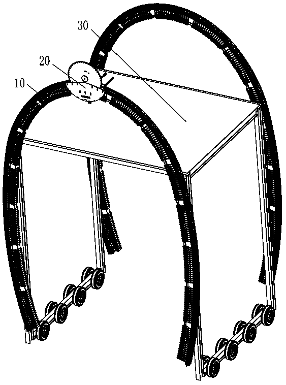
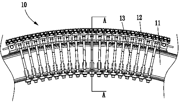
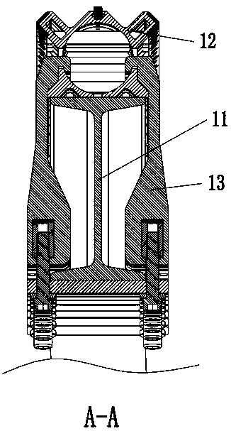
The invention provides an arc-shaped track wall-sawing machine. Through machining a track into a keel shape, the track is curved to a radian attached to an arc-shaped track bed, the supporting intensity of the track does not changed, and the track is reusable. The track bed is segmented and convenient to install and disassemble. A wall-sawing machine head can be disassembled and installed rapidly,a suitable gap is formed between the outer cambered surface of an arc-shaped track and the inner wall of a tunnel, and the arc-shaped track and a trolley moving in the tunnel is convenient. A motor in-out oil pipe is vertically arranged in the section direction of the arc-shaped track, cutting of the wall-sawing machine does not be affected, and the thickness of the wall-sawing machine head is compressed to enable the wall-sawing machine head to have the maximum passing ability. A meshing center of a feeding gear and a rack is on the center section of left and right wheels to avoid the feeding gear breaking away from the rack or getting stuck caused by changing of the track radian. The arrangement of an elastic adjustment device enables rollers to mesh with multi-radian arc-shaped tracks,the feeding gear on the center of the two rollers is ensured, and the problem of shield protection is further solved.

Description

technical field [0001] The invention relates to the field of track technology, in particular to an arc track wall sawing machine. Background technique [0002] During the long-term use of road tunnels, railway tunnels, and high-speed rail tunnels, some tunnel repairs or upgrades require stripping of the original tunnel walls. The conventional method is to use a gun to break or use a wall saw to install a one-meter-long straight track. For segmental cutting, there is also the way of cutting multi-arc arc track with wall saw machine. The multi-arc arc track cutting is static cutting, which will not damage the buildings that need to be preserved. It can cut reinforced concrete and steel structures. When cutting tunnels , can fit the tunnel arc and perform multi-arc cutting according to the tunnel arc, but the multi-arc arc track cutting in the prior art has the following problems: the distance between the arc track and the inner wall of the tunnel is about 10cm, and when the tr...

Claims


Application Information

Patent Timeline
IPC IPC(8): B28D1/04B28D7/02B28D7/00
CPCB28D1/04B28D7/00B28D7/02
Inventor 陈立军
Owner VOPEN ENG EQUIP CO LTD
Why Eureka
Eureka Blog
Learn More