Auxiliary brake device and system

A technology for assisting brakes and brake connecting rods, which is applied to foot-actuated starting devices, automatic starting devices, braking action starting devices, etc., can solve problems such as affecting the work efficiency of trainers, inconvenient installation of brake pedals, and affecting the use of brake pedals. Achieve the effect of improving reliability and safety, eliminating potential safety hazards and taking up less space

Pending Publication Date: 2018-11-13
DUOLUN TECH CO LTD
View PDF0 Cites 3 Cited by
  • Summary
  • Abstract
  • Description
  • Claims
  • Application Information

AI Technical Summary

Problems solved by technology

However, the coach is prone to fatigue after sitting in the co-pilot seat for a long time, which greatly affects the work efficiency of the coach and virtually leaves a safety hazard
[0005] In daily life, when driving on the highway, many drivers will use the cruise control function, which reduces the fatigue of the driver, but the cruise control function cannot ensure that the car keeps a safe distance from the vehicle in front. Once the driver appears If the driver is slack, rear-end collision accidents are likely to occur; at the same time, when the driver is driving in the city, because there are many intersections, the frequency of waiting for traffic lights is very high, and the driver needs to frequently pull up and put down the parking brake, which is prone to fatigue; When waiting for traffic lights, if you forget to pull up the parking brake, when the rear vehicles do not brake in time, it is easy to cause a series of rear-end collision accidents; when waiting for traffic lights on a sloped road, if you forget to pull up the parking brake, it is easy to slip. Car phenomenon, there is a safety hazard
[0006] For this reason, the application of auxiliary braking systems / devices in automobiles is particularly important. The above-mentioned problems are overcome through auxiliary braking systems / devices. At present, some manufacturers are also developing auxiliary braking devices by themselves, but most of the devices have complex structures and volume Large, not easy to install on the brake pedal, and the larger volume will affect the use of the brake pedal during use

Method used


Image

  • Auxiliary brake device and system
  • Auxiliary brake device and system
  • Auxiliary brake device and system

Examples


Embodiment Construction

[0036] In order to facilitate the understanding of those skilled in the art, the present invention will be further described below in conjunction with the embodiments and accompanying drawings, and the contents mentioned in the embodiments are not intended to limit the present invention.

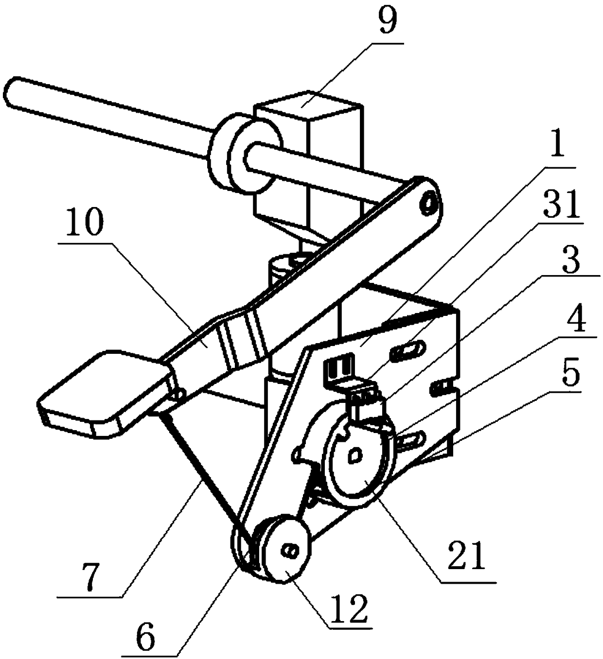
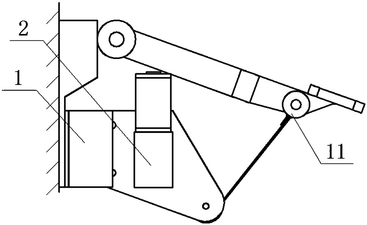
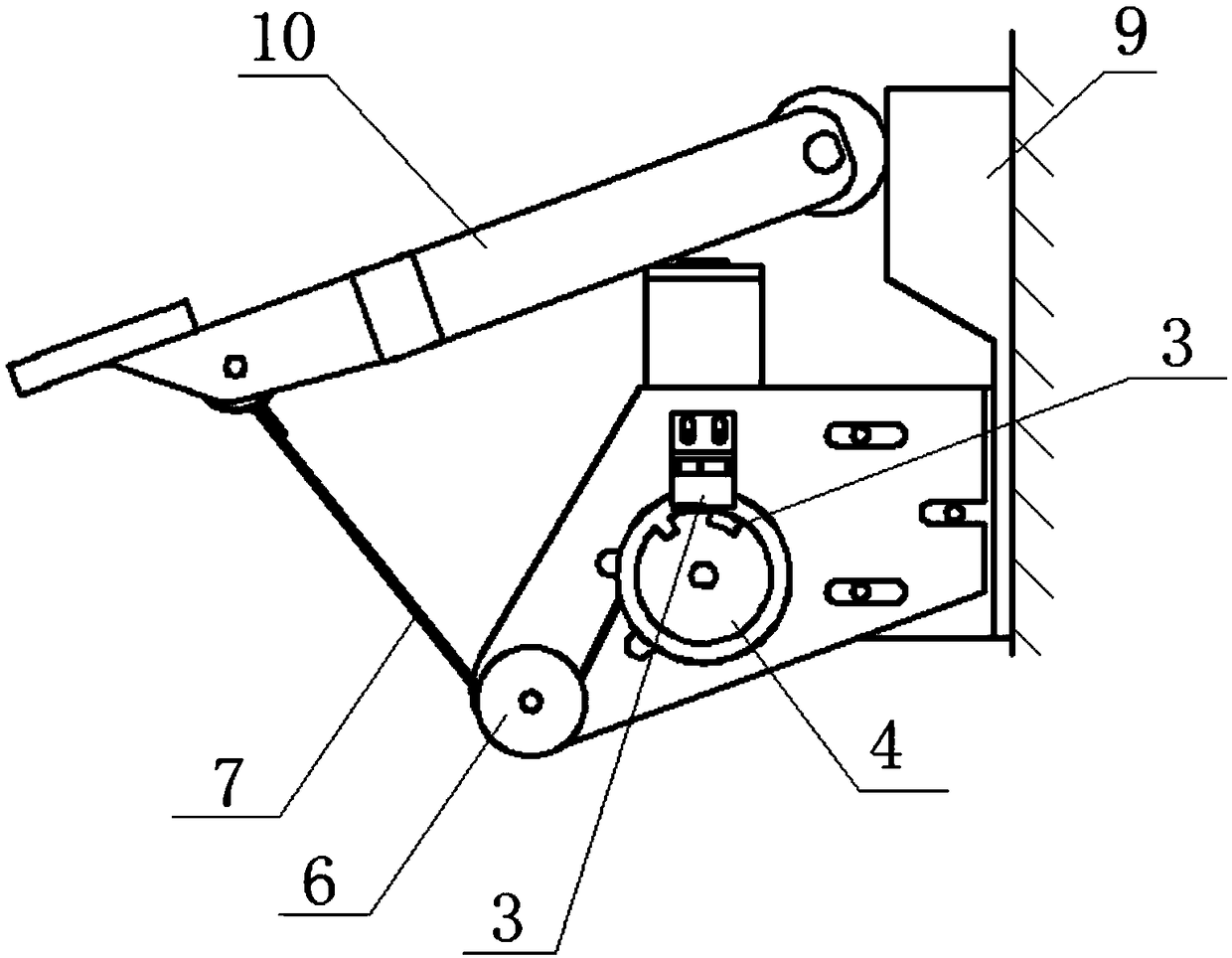
[0037] refer to Figure 1 to Figure 4 As shown, an auxiliary braking device of the present invention can be applied to most vehicles on the market, and can also be applied to motor vehicle driver training vehicles; in Example 1, the device is applied to motor vehicle driver training vehicles , installed at the co-pilot position of the vehicle, including: support plate 1, worm gear motor 2, micro switch 3, motor wheel 4, motor wheel cover 5, transition wheel 6, wire rope 7 and controller 8; support plate 1 passes The connecting rod bracket 9 is fixed on the car body near the brake of the co-pilot position; the worm gear motor 2 is fixed on one side of the support plate 1, and the output shaft...


PUM


Abstract

The invention discloses an auxiliary brake device and system. The auxiliary brake device comprises a supporting plate, a worm-gear reduction motor, a microswitch, a motor wheel, a motor wheel cover, atransitional wheel, a steel wire rope and a controller; the worm-gear reduction motor is fixed on one side surface of the supporting plate; an output shaft of the worm-gear reduction motor penetratesthrough the supporting plate; the microswitch, the motor wheel, the motor wheel cover and the transitional wheel are fixed on the other side surface of the supporting plate; and the worm-gear reduction motor drives the motor wheel to pull a braking connecting rod through the steel wire rope to realize braking. The auxiliary brake device has a small structure, is easily mounted, is suitable for different vehicle models and can also be mounted on a main driving seat braking pedal or a sub driving seat braking pedal according to needs; and therefore, the driving safety is enhanced.

Description

technical field [0001] The invention relates to an auxiliary braking device and system, belonging to the technical field of vehicle braking equipment. Background technique [0002] Braking, commonly known as "braking", is the action of stopping or reducing the speed of running locomotives, vehicles and other means of transportation or machinery. The brake pedal of the car is under the steering wheel, and when the brake pedal is stepped on, the brake lever is linked and pressed and transmitted to the brake pads on the brake drum to block the brake wheel, so that the car slows down or stops running. [0003] Now more and more private cars are entering the life, leading to the increasing congestion of urban traffic; however, the uneven driving ability of motor vehicle drivers and the inattention of drivers often lead to traffic accidents; minor accidents lead to vehicle collisions, Severe accidents can result in vehicle crashes and fatalities. According to statistics from rel...

Claims


Application Information

Patent Timeline
IPC IPC(8): B60T7/04B60T7/22
CPCB60T7/22B60T7/042
Inventor 姬国栋文政宋智王国策许宇飞杨宏伟范正宇盛艳萍
Owner DUOLUN TECH CO LTD
Why Eureka
Try Eureka