Hydraulic automobile co-pilot brake device

A brake device and hydraulic technology, applied in the field of automobile brake devices, can solve the problems of difficulty in adapting to different models, large frictional resistance, damage to the car body, etc., and achieve the effects of convenient disassembly and assembly, small occupied space and simple structure

Pending Publication Date: 2018-11-13
SOUTHWEST PETROLEUM UNIV
View PDF6 Cites 1 Cited by
  • Summary
  • Abstract
  • Description
  • Claims
  • Application Information

AI Technical Summary

Problems solved by technology

The above-mentioned auxiliary brake devices for automobiles all have the following deficiencies: (1) the metal bracket is fixed by bolts, screws or welding, which damages the car body and affects the appearance and reliability of the car body; (2) the installation and fixing of the metal bracket are not easy, It is necessary to understand the structure of the car body before drilling and screwing or welding. It is also very troublesome to weld or drill holes in the narrow car body, which is not suitable for non-professionals; It is troublesome for private car owners who temporarily need the co-pilot brake; (4) The existing easy-to-disassemble co-pilot brake device needs to be fixed on the beam between the two cabs through a splint, which is difficult to adapt to different models; (5) Pull wire transmission mode The mechanical conduction performance is not good, and most of the pulleys are used, and the frictional resistance is large

Method used


Image

  • Hydraulic automobile co-pilot brake device
  • Hydraulic automobile co-pilot brake device
  • Hydraulic automobile co-pilot brake device

Examples


Embodiment Construction

[0020] Below in conjunction with accompanying drawing, the embodiment of the present invention is described further:

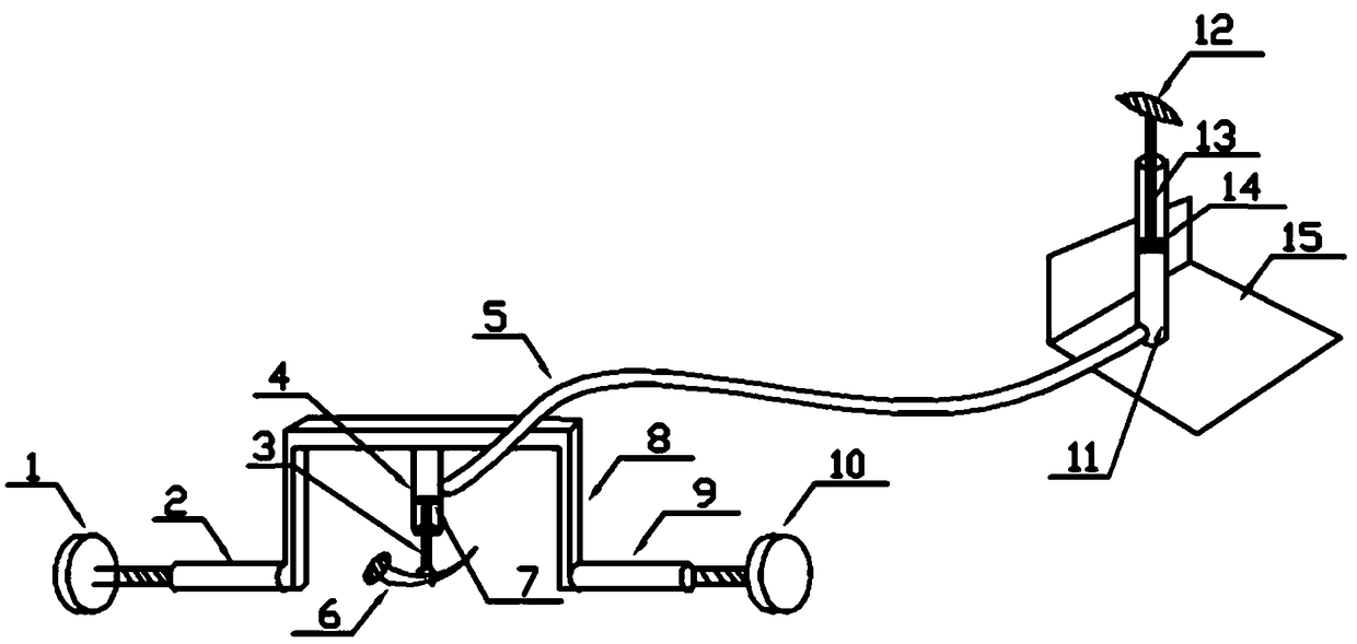
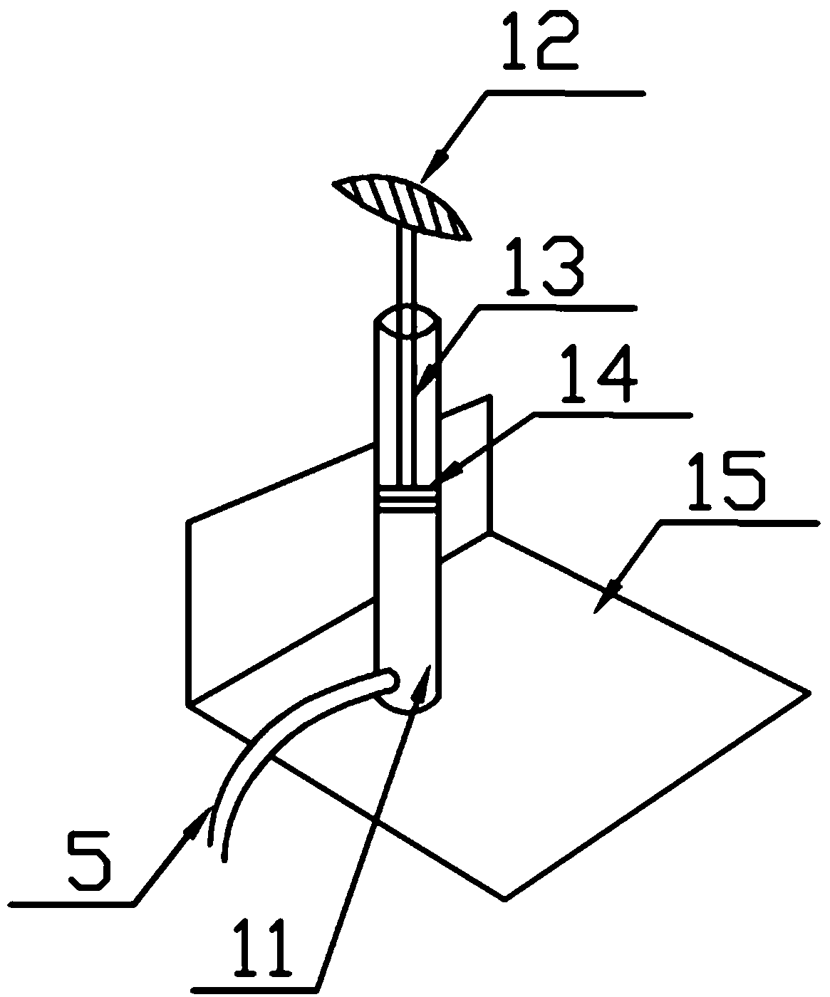
[0021] like figure 1 As shown, a hydraulic vehicle co-pilot brake device according to the present invention includes a main driver part, a co-pilot part, and an infusion tube; Before, the infusion tube 5 is connected with the main driving part and the copilot part.

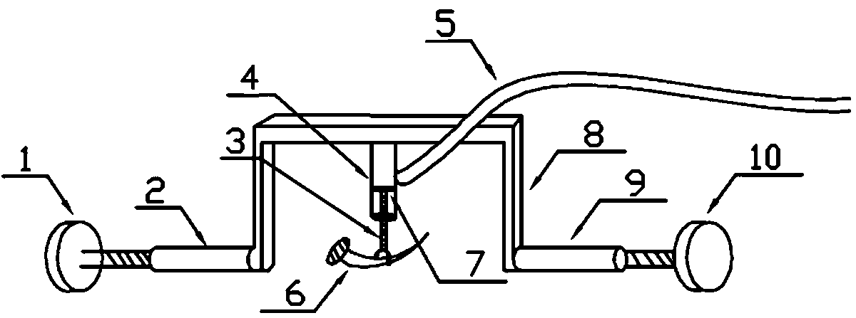
[0022] refer to figure 2 , the main driving parts include a first support bolt 1, a first sleeve 2, a fork lever 3, a first hydraulic cylinder 4, a first piston 7, a convex frame 8, a second sleeve 9, and a second support bolt 10 . Wherein, both the first sleeve and the second sleeve 9 have internal threads, and the first support bolt 1 and the second support bolt 10 are respectively screwed into the corresponding sleeves, and the heads of the two support bolts are flat and the end faces are rough, so they can be screwed with a wrench or Manually rotate to change the length of the two bolts p...


PUM


Abstract

The invention relates to a hydraulic automobile co-pilot brake device. The hydraulic automobile co-pilot brake device comprises a main driving braking part, a co-pilot braking part and a liquid transport pipe. The main driving braking part mainly comprises an inverted T-shaped frame, a hydraulic cylinder, a piston and a fork rod, and is supported on the two walls of a cab through screwing connection of bolts and sleeves; and the co-pilot braking part mainly comprises a pedal, a hydraulic cylinder, a piston and a piston rod, and provides supporting force through an angle plate. When the pedal of co-pilot is stepped or released, compressed liquid flows between the two hydraulic cylinders through the liquid transport pipe for extrusion to drive the pistons to move, and thus the purpose of controlling the main driving brake is achieved. The hydraulic automobile co-pilot brake device has a simple structure, a simple fixing mode, convenient installation and excellent mechanical conductive property.

Description

technical field [0001] The invention relates to the technical field of automobile braking devices, in particular to a hydraulic type automobile co-driver braking device. Background technique [0002] At present, in various auxiliary brake devices of automobiles, different types of metal brackets are installed at the main and auxiliary driving positions to support and fix the transmission cables between the main and auxiliary brake pedals. The above-mentioned auxiliary brake devices for automobiles all have the following deficiencies: (1) the metal bracket is fixed by bolts, screws or welding, which damages the car body and affects the appearance and reliability of the car body; (2) the installation and fixing of the metal bracket are not easy, It is necessary to understand the structure of the car body before drilling and screwing or welding. It is also very troublesome to weld or drill holes in the narrow car body, which is not suitable for non-professionals; It is trouble...

Claims


Application Information

Patent Timeline
Patent Type & Authority Applications(China)
IPC IPC(8): B60T7/06B60T11/10
CPCB60T11/10B60T7/06
Inventor 刘浩毛正林李乾程俊霖李仁明潘洁
Owner SOUTHWEST PETROLEUM UNIV
Why Eureka
Try Eureka