Screw-rod-driven roller bit

A technology of roller cone bit and screw drive, which is applied in the direction of drill bit, driving device for drilling in borehole, drilling equipment, etc. It can solve the problems of bit torque and speed weakening, small fluid displacement, unfavorable rock breaking, etc., to overcome High friction resistance and rock breaking efficiency

Active Publication Date: 2018-11-13
中石化石油工程技术服务有限公司 +2
View PDF5 Cites 0 Cited by
  • Summary
  • Abstract
  • Description
  • Claims
  • Application Information

AI Technical Summary

Problems solved by technology

[0003] The current problem is that if you want to increase the impact times of the teeth on the rock, you can only increase the drill bit speed; the friction between the drill tool and the well wall weakens the torque and speed on the drill bit, which cannot be kept stable, which is not conducive to rock breaking ;When the fluid displacement in the drilling tool is small or no, the annulus is easy to form grit to landfill the drilling tool

Method used


Image

  • Screw-rod-driven roller bit
  • Screw-rod-driven roller bit

Examples


Embodiment 1

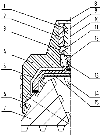
[0022] Refer to attached figure 1 , the screw driven roller cone bit of the present invention comprises a body 4, a roller cone 7, a water inlet 8 and a nozzle 14, a screw power motor is housed in the water inlet 8, and the stator 7 of the screw power motor is embedded in the inner wall of the water inlet 8 Above, the rotor 1 protrudes downwards into the body 4 . A sealed inner cavity 15 is arranged inside the body 4, and a transmission disc 5 is housed in the inner cavity 15, and the transmission disc 5 and the body 4 form a rotating and sealed fit. The rotor 1 is connected with the drive disc 5 through the coupling 12 and the cardan shaft 13 in turn, the upper end of the drive disc 5 is fixedly connected with the cardan shaft 13 to form a shaft drive to transmit torque, and the lower section is provided with teeth. The coupling 12 is a spline structure and transmits torque together with the cardan shaft 13 . There is a driven gear 6 at one end of the cone 7, and the driven...

Embodiment 2

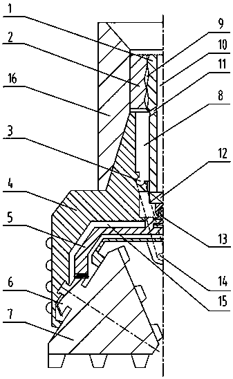
[0025] Another embodiment of the present invention refers to the attached figure 2 , The difference from Embodiment 1 is that the screw joint 16 is threaded above the drill bit, and the stator 2 is installed inside the screw joint 16 . In fact, the runner rubber of the stator 2 is directly vulcanized and molded on the inner wall of the screw nipple 16, and the rotor 1 is installed in the stator 2 and extends downward into the water inlet hole 8 of the drill bit to transmit torque to the drive disc 5. A bypass valve can also be added above the screw pup joint 16 to realize the internal and external pressure balance of the drilling tool when tripping.

[0026] The number of cones in the above-mentioned embodiments is one or more. It can be a single cone bit, a symmetrically arranged double cone bit, or a common three-cone bit. The number of cones can also be more than three.

[0027] The working process of the present invention is as follows: the screw-driven roller cone bit i...


PUM


Abstract

The invention discloses a screw-rod-driven roller bit. According to the technical scheme, the screw-rod-driven roller bit comprises a roller cone and a body, and further comprises a stator and a rotor; the stator is fixed relative to the body, and the stator and the rotor constitute a screw rod power motor; the rotor and the roller cone constitute rotary transmission fit, the rotor is connected with a transmission disc through a universal shaft to constitute shaft transmission, and the transmission disc and the roller cone constitute gear transmission; the body is provided with an inner cavity, wherein the inner cavity and a water inlet hole are isolated; and the transmission disc is mounted in the inner cavity and is in rotary sealing fit with the body, the roller cone is provided with adriven gear, and the roller cone and the transmission disc constitute gear transmission through the driven gear. The screw-rod-driven roller bit plays an important role in expanding the function and application of the roller bit and promoting the progress of the well drilling industry; and the friction resistance of a drill tool and the well wall can be overcome, the rock breaking efficiency is improved, and mud fluid circulation in the bit is still ensured when a pump has no displacement.

Description

technical field [0001] The invention relates to a drill bit, in particular to a screw driven roller cone bit, which is suitable for the field of oil mine drilling. Background technique [0002] The traditional roller cone bit in the drilling industry can only rotate passively while the roller cone is revolving. Under the action of the weight on bit and the rotation of the drill string, the teeth crush and eat into the rock, and at the same time produce a certain amount of sliding to shear the rock. The rock-breaking mechanism of the traditional roller cone bit: When the roller cone bit revolves, the cone rotates passively. Under the action of the drilling pressure and the rotation of the drill string, the teeth crush and eat into the rock, and at the same time, a certain amount of sliding is generated to shear the rock. When the cone rolls at the bottom of the well, the teeth on the cone impact and press into the formation in turn. This action crushes a part of the rock at t...

Claims


Application Information

Patent Timeline
IPC IPC(8): E21B10/08E21B10/18E21B4/02
CPCE21B4/02E21B10/08E21B10/18Y02P70/10
Inventor 曲刚李亚伟李荣刚曾飞舟
Owner 中石化石油工程技术服务有限公司
Why Eureka
Try Eureka