Tunnel lining trolley with material distribution device

A technology of material distribution device and lining trolley, which is applied in the direction of tunnel lining, tunnel lining, shaft lining, etc., can solve the problems of high labor intensity, low work efficiency, and slow cement conveying speed, and achieve the goal of reducing labor intensity and improving work efficiency Effect

Inactive Publication Date: 2018-11-13
FUJIAN JIANGLE YUANBO ENG MACHINERY MFG CO LTD
View PDF1 Cites 0 Cited by
  • Summary
  • Abstract
  • Description
  • Claims
  • Application Information

AI Technical Summary

Problems solved by technology

However, the existing tunnel lining trolley needs to manually mix the cement, then pour the cement into a specific pipeline, and inject the mixed cement into the discharge port provided on the arc formwork unit through a specific channel, and then Flowed into the wall of the tunnel, the above-mentioned operation process shows that the shortcomings of the existing tunnel lining trolley are: during operation, for the construction personnel, the labor intensity is high and the work efficiency is low.
[0004] In view of the above situation, the patent application number is 201620242714.8, the patent name is a patent for a tunnel lining trolley equipped with a material distribution device, and a corresponding solution is proposed, but in the actual implementation, there are still deficiencies, which is the first When the conveying device and the second conveying device are conveying cement, the cement conveying speed is slow, which will cause the cement to solidify, causing the cement to be blocked in the first conveying device and the second conveying device, affecting the development of the entire construction period

Method used


Image

  • Tunnel lining trolley with material distribution device

Examples


Embodiment Construction

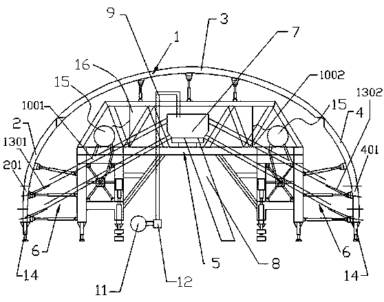
[0016] Attached below figure 1 The present invention is described in further detail.

[0017] as attached figure 1 As shown, the present invention is a tunnel lining trolley with a material distribution device, which includes an arc-shaped formwork unit 1, a skeleton unit 5 and an adjustment support unit 6; The first side template group 2, the top template 3 and the second side template group 4;

[0018] The adjustment support unit 6 is arranged between the skeleton unit 5 and the template unit 1, and is configured to push the first side template group 2, the top template group 3 and the second side template group 4 outward according to the size of the tunnel section. Move to make it stick to the lining of the tunnel; the skeleton unit 5 is equipped with a charging and distributing device 7 with stirring function, and the charging and distributing device 7 is connected with a A cement conveying device 8 for cement and a delivery pipe 9 for delivering water to the charging a...


PUM


Abstract

The invention discloses a tunnel lining trolley with a material distribution device. The tunnel lining trolley comprises a skeleton unit (5) and a loaded material distribution device (7). A cement conveying device (8) used for conveying cement to the loaded material distribution device (7) and a conveying pipe (9) used for conveying water to the loaded material distribution device (7) are connected to the loaded material distribution device (7). First conveying devices (1001) used for conveying stirred materials to first discharging outlets (201) formed in a first lateral formwork set (2) andsecond conveying devices (1002) used for conveying the stirred materials to second discharging outlets (401) formed in a second lateral formwork set (4) are further connected to the loaded material distribution device (7). Corresponding air pumps (15) are arranged. The tunnel lining trolley has the advantages that the labor intensity of on-site constructors is greatly reduced, the working efficiency is improved, the cement conveying-out rate is increased, and the cement is not liable to be solidified in the conveying process.

Description

technical field [0001] The invention relates to tunnel construction equipment, in particular to a tunnel lining trolley with a material distributing device. Background technique [0002] The tunnel lining trolley belongs to the special equipment that must be used in the secondary lining of the tunnel construction process, and is used for the lining construction of the inner wall of the tunnel. [0003] At present, the existing tunnel lining trolley mainly includes a skeleton unit, an arc-shaped formwork unit composed of a top formwork, two side forms and two bottom formworks, and a liftable support unit connecting the formwork unit and the skeleton unit. The support unit can push each side formwork to swing outwards with the corresponding bottom formwork, so that the outer contour of the formwork unit expands outwards, so as to fit tunnels of different sizes and sections. However, the existing tunnel lining trolley needs to manually mix the cement, then pour the cement into...

Claims


Application Information

Patent Timeline
IPC IPC(8): E21D11/10E21D11/40
CPCE21D11/10E21D11/40
Inventor 廖国华
Owner FUJIAN JIANGLE YUANBO ENG MACHINERY MFG CO LTD
Why Eureka
Try Eureka