Flow control valve

A flow control valve and valve body technology, which is applied in the direction of coolant flow control, valve details, multi-way valve, etc., can solve the problems of poor installation workability and achieve the effect of improving installation workability

Active Publication Date: 2018-11-13
HITACHI ASTEMO LTD
View PDF5 Cites 2 Cited by
  • Summary
  • Abstract
  • Description
  • Claims
  • Application Information

AI Technical Summary

Problems solved by technology

[0006] However, in the prior art described above, the piping constituting the lower return path is separated from the housing of the first control valve, so it is necessary to install the piping separately from the housing, resulting in poor installation workability. such problem

Method used


Image

  • Flow control valve
  • Flow control valve
  • Flow control valve

Examples


Embodiment approach 1

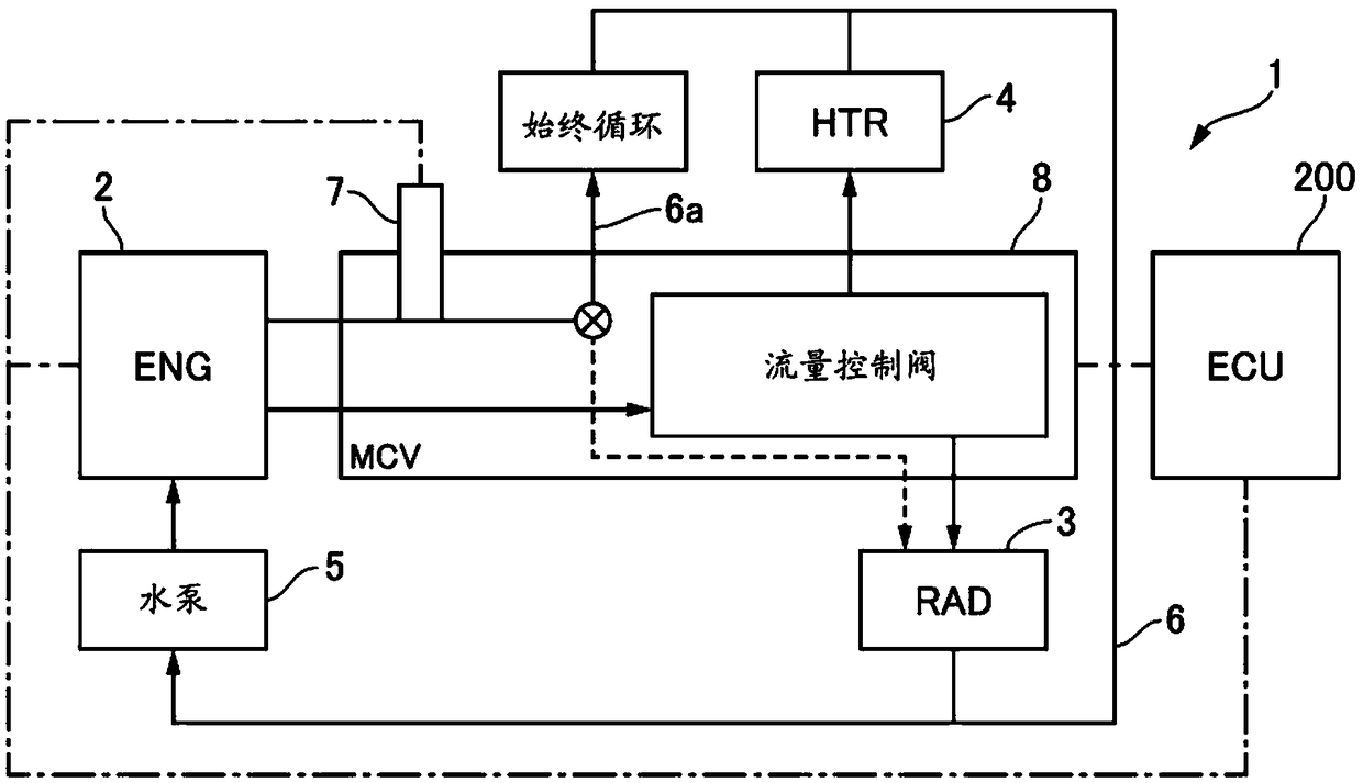
[0033] figure 1 It is a schematic diagram of the cooling system 1 of Embodiment 1.

[0034] The cooling system 1 according to the first embodiment has a circuit 6 for returning the cooling water cooled by the engine 2 as a heat source to the engine 2 via the water pump 5 after passing through a plurality of heat exchangers (radiator 3 and heater 4 ). The engine 2 is, for example, a gasoline engine, and is mounted on a vehicle. The radiator 3 cools the cooling water through heat exchange between the cooling water and the traveling wind. When the heater 4 heats the interior of the vehicle, the cooling water is cooled by heat exchange between the cooling water and the air blown into the vehicle interior. The water pump 5 is rotationally driven by the driving force of the engine 2 and supplies cooling water from the radiator 3 and the heater 4 to the engine 2 . The circuit 6 has a normally open water channel 6a, which bypasses the heat exchangers 3, 4 and is used to circulate t...

Embodiment approach 2

[0072] Next, Embodiment 2 will be described. The basic structure of Embodiment 2 is the same as that of Embodiment 1, so only the parts that differ from Embodiment 1 will be described.

[0073] Figure 8 It represents MCV8 of Embodiment 2 Figure 4 The S6-S6 line view sectional view, Figure 9 It is a front view of the cover 51 of Embodiment 2. In the MCV8 of the second embodiment, the shape of the cover 51 is different from that of the first embodiment. The cover 51 has an R-shaped portion 65 inside it. The R-shaped portion 65 smoothly connects the inner peripheral surface of the cylindrical portion 52 and the inner side surface of the flange portion 53 with a curved surface having a predetermined curvature. The center of curvature of the R-shaped portion 65 is on the inner side of the cover 51 .

[0074] The flange portion 53 of Embodiment 2 has a rotationally asymmetric shape with respect to a point on the central axis O when viewed from the axial direction of the cyl...

Embodiment approach 3

[0079] Next, Embodiment 3 will be described. The basic structure of Embodiment 3 is the same as that of Embodiment 1, so only the parts that differ from Embodiment 1 will be described.

[0080] Figure 10 It represents MCV8 of Embodiment 3 Figure 4 The S6-S6 line view sectional view. The MCV 8 according to Embodiment 3 differs from Embodiment 1 in that the gap between the second opening 38 and the internal communication port 50 is not sealed. Specifically, MCV8 of Embodiment 3 does not have figure 1 and Image 6 The sealing member 58 shown in. Accordingly, cost reduction can be achieved by reducing the number of components.


PUM


Abstract

Provided is a flow control valve which improves a mounting efficiency. An MCV (8) includes a housing (10) including a valve-element housing portion (44), a first communicating aperture (46) which introduces cooling water, which is flown out of a first water channel (2a) formed in an engine, to the valve-element housing portion (44), and a second communicating aperture (47) which discharges the cooling water in the valve-element housing portion (44) to a second water channel (2b) formed in the engine; a rotor (12) accommodated in the valve-element housing portion and configured to change a flowrate of the cooling water discharged to the second water channel (2b), according to a rotation angle of the rotor; and a drive mechanism (11) configured to control the rotation angle of the rotor (12). The first and second communicating apertures (46, 47) open in an engine-side mounting surface (16a) of the housing (10).

Description

technical field [0001] The present invention relates to flow control valves. Background technique [0002] Patent Document 1 discloses a thermostat device that is provided on a cooling circulation path of an engine and includes a first control valve that controls the flow rate of coolant passing through a radiator. This thermostat device has a lower side return path for returning coolant flowing out of the engine when the engine is started. [0003] prior art literature [0004] patent documents [0005] Patent Document 1: Japanese Patent Laid-Open No. 2002-129956 [0006] However, in the prior art described above, the piping constituting the lower return path is separated from the housing of the first control valve, so it is necessary to install the piping separately from the housing, resulting in poor installation workability. such a problem. Contents of the invention [0007] One object of the present invention is to provide a flow control valve capable of improvin...

Claims


Application Information

Patent Timeline
Patent Type & Authority Applications(China)
IPC IPC(8): F01P7/14F01P7/16
CPCF01P7/14F01P7/165F01P2007/146F16K11/0856F16K27/065F16K31/043F01P3/20F01P2060/18
Inventor 申振宇村上信吾中村英昭
Owner HITACHI ASTEMO LTD
Why Eureka
Try Eureka