High gain microstrip antenna with short circuit pin

A technology of microstrip antenna and short-circuit pin, applied in the field of communication, can solve the problems of low radiation efficiency, narrow bandwidth, low gain of microstrip antenna, etc., and achieve the effect of improving radiation performance, high gain, and increasing antenna gain

Inactive Publication Date: 2018-11-13
FOSHAN SHUNDE SUN YAT SEN UNIV RES INST +2
View PDF2 Cites 1 Cited by
  • Summary
  • Abstract
  • Description
  • Claims
  • Application Information

AI Technical Summary

Problems solved by technology

[0002] Because the traditional microstrip antenna has defects such as low gain, narrow bandwidth, and low radiation efficiency, it is limited in many applications
At present, the technology of integrating shorting pins on the microstrip antenna has appeared. Compared with the traditional microstrip antenna, although it improves the gain, it cannot accurately make the antenna gain reach a higher level. In actual communication, people require It is not just that the gain is increased, but the antenna gain is expected to reach the maximum or approximate maximum, so that its radiation performance can be optimized, and more energy can be emitted in a narrow range.

Method used


Image

  • High gain microstrip antenna with short circuit pin
  • High gain microstrip antenna with short circuit pin
  • High gain microstrip antenna with short circuit pin

Examples


Embodiment Construction

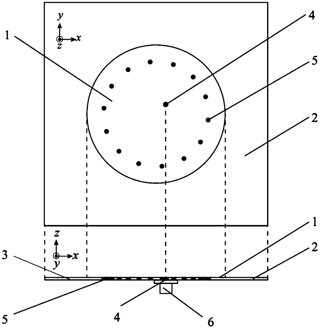
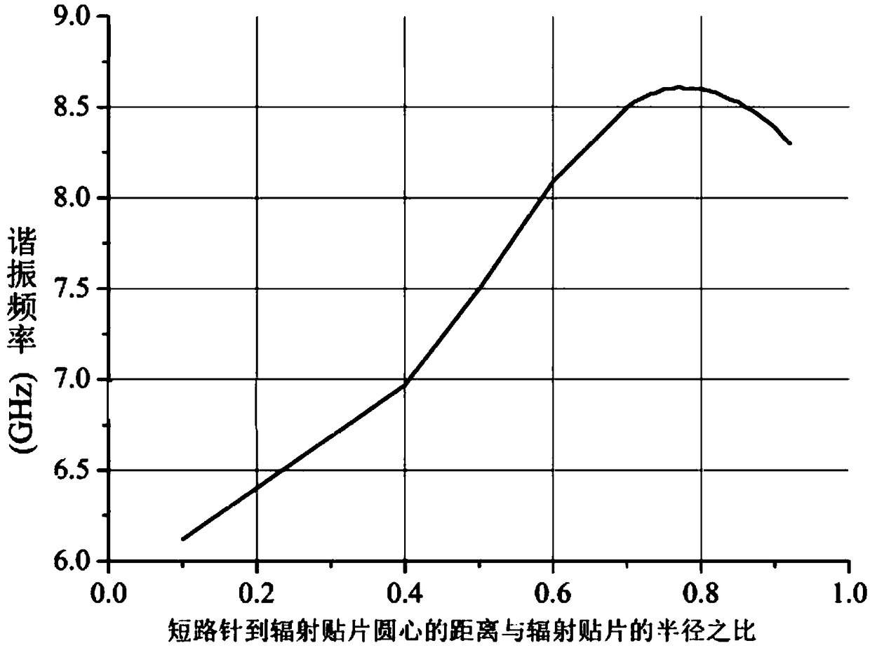
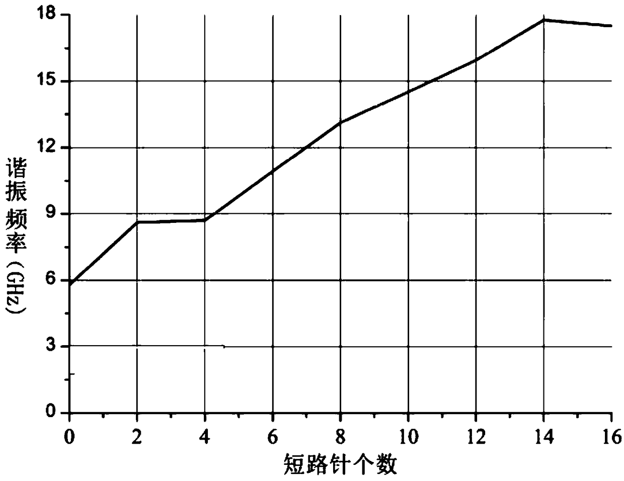
[0019] refer to Figure 1-Figure 6 , a high-gain microstrip antenna with a short-circuit pin of the present invention includes an antenna, and the antenna includes a radiation patch 1 with a circular transverse section, a dielectric substrate 2, a short-circuit pin 5, a feed ground 3 and the The radiation patch 1 is provided coaxially with the feeding conductor pin 4; the radiation patch 1 is arranged on the upper surface of the dielectric substrate 2, the feeding ground 3 is arranged on the bottom surface of the dielectric substrate 2, and the feeding conductor One end of the body needle 4 is connected to the radiation patch 1 and the other end is connected to the feed ground 3 through the dielectric substrate 2; the radiation patch 1 is provided with one piece, and the number of the short-circuit pins 5 is fourteen, and the short-circuit The ratio of the distance from the needle 5 to the center of the radiation patch 1 to the radius of the radiation patch 1 is 0.7-0.8; the f...


PUM


Abstract

The invention discloses a high gain microstrip antenna with a short circuit pin. The high gain microstrip antenna with a short circuit pin comprises an antenna, wherein the antenna comprises a radiation patch with a circular transverse profile, a dielectric substrate, short circuit pins, a feed ground and a feed conductor pin, wherein the feed conductor pin and the radiation patch are arranged coaxially; the radiation patch is closely fastened to the upper surface of the dielectric substrate; the feed ground is arranged on the bottom surface of the dielectric substrate; one end of the feed conductor pin is connected to the radiation patch, and the other end of the feed conductor pin is connected to the feed ground after penetrating the dielectric substrate; the number of the radiation patch is 1, and the number of the short circuit pins is 14; the ratio between the distance from the short circuit pins to the center of circle of the radiation patch and the radius of the radiation patchis 0.7-0.8; and the 14 short circuit pins are uniformly arranged on the edge of the radiation patch in a ring shape. The high gain microstrip antenna with a short circuit pin can further increase theantenna gain and can improve the radiation performance.

Description

technical field [0001] The invention relates to the communication field, in particular to a high-gain microstrip antenna with a short-circuit pin. Background technique [0002] Because the traditional microstrip antenna has defects such as low gain, narrow bandwidth, and low radiation efficiency, it is limited in many applications. At present, the technology of integrating shorting pins on the microstrip antenna has appeared. Compared with the traditional microstrip antenna, although it improves the gain, it cannot accurately make the antenna gain reach a higher level. In actual communication, people require It is not just that the gain is increased, but the antenna gain is expected to reach the maximum or approximate maximum, so that its radiation performance can be optimized and more energy can be emitted in a narrow range. Contents of the invention [0003] In order to solve the above problems, the object of the present invention is to provide a high-gain microstrip an...

Claims


Application Information

Patent Timeline
Patent Type & Authority Applications(China)
IPC IPC(8): H01Q1/38H01Q1/48H01Q1/50
CPCH01Q1/38H01Q1/48H01Q1/50
Inventor 谭洪舟黄静文区俊辉张全琪路崇
Owner FOSHAN SHUNDE SUN YAT SEN UNIV RES INST
Why Eureka
Try Eureka