Power grid layout structure and system based on ice-melting function

A technology for arranging structure and melting ice, which is applied in the installation of electrical components, cables, overhead installation, etc. It can solve the problems of short ice melting distance, on-site icing, and long time consumption, so as to extend the ice melting distance and reduce the circuit impedance. , the effect of increasing the ice melting speed

Pending Publication Date: 2018-11-13
GUANGDONG POWER GRID CO LTD +1
View PDF0 Cites 1 Cited by
  • Summary
  • Abstract
  • Description
  • Claims
  • Application Information

AI Technical Summary

Problems solved by technology

[0004] (1) The ice-melting voltage is only 400V. According to the calculation of LGJ70--95 wire in the common ice-walking area, it can only melt ice for about 1.3 kilometers, but the most common ice-walking area is about 2-5 kilometers, and the ice-melting distance is too large. Short, to be carried out step by step, time-consuming and slow;
[0005] (2) The labor intensity of the workers is high, the work efficiency is low, and there is ice on the site, the working environment is poor, and the risk of working safety is great
[0006] To sum up, the existing technology lacks an efficient means of melting ice to meet the emergency demand for power supply in extreme weather such as ice disasters

Method used


Image

  • Power grid layout structure and system based on ice-melting function
  • Power grid layout structure and system based on ice-melting function
  • Power grid layout structure and system based on ice-melting function

Examples


Embodiment 1

[0046] In the embodiment of the present invention, the voltage on the non-ice-melting side of the transformer is the voltage that provides the ice-melting power supply, and the ice-melting side provides the ice-melting voltage. Here, what affects the ice-melting distance is the ice-melting voltage on the ice-melting side. However, it should be noted that the non-ice-melting side actually only represents the input side of electric energy, and the ice-melting side is the output side of the power supply. In practical applications, the non-ice-melting side can also be used as the ice-melting side, or the ice-melting side The side is the ice-melting side, that is, the ice-melting side can be either the primary side of the transformer or the secondary side of the transformer. For the convenience of expression and understanding, the embodiment of the present invention uses the ice-melting side as one end of the output ice-melting voltage to melt the ice.

[0047] The grid layout stru...

Embodiment 2

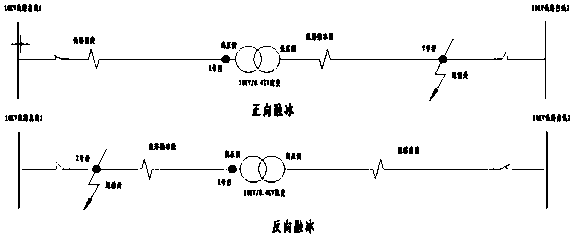
[0068] refer to Figure 5 As shown, the 10kv / 0.4kv distribution transformer is used as the ice melting transformer, 0.4kv is the ice melting voltage, the ice melting wire is LGJ-70, the wire impedance is 0.587Ω / km, the distribution transformer capacity is 200KVA, and the three-phase direct short circuit is full load Melting ice, the melting distance is 1.36km, the principle is as follows Figure 8 shown.

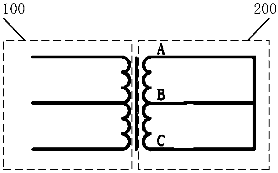
[0069] The power grid layout system based on the ice melting function of the present invention includes the power grid layout structure based on the ice melting function as described above, and also includes:

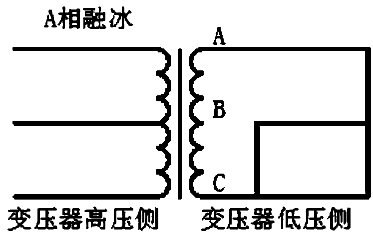
[0070] The transformer's A-phase ice-melting side line, B-phase ice-melting side line and C-phase ice-melting side line are switched in turn and connected in parallel to reduce the total impedance of the circuit, so as to extend the ice-melting distance of the wire by 1.33 times, and the ice-melting distance is extended from the original 1.36km to 1.8km, the princip...


PUM


Abstract

The invention provides a power grid layout structure and system based on an ice-melting function. The power grid layout structure and system comprises a transformer non-melting side three-phase line providing an ice melting power source and a transformer melting side three-phase line; and two phase lines of the transformer melting side three-phase line are connected in parallel by a rotation conversion mode, and the two phases in parallel and the non-parallel phase form an operating loop, thereby reducing the impedance of the loop, and achieving the effects of extending the melting distance and increasing the melting speed. The power grid layout structure and system effectively solve the problem of ice melting in extreme weather such as ice disaster by means of parallel operation and phaseloss operation; compared with three-phase direct short-circuit ice melting, the power grid layout structure and system not only significantly prolong the melting distance, but also increases the three-phase ice melting speed more efficiently; and the power grid layout structure and system guarantee the ice melting effect of transmission and distribution lines of different voltage levels, are simple and easy in operation, low in safety risk and wide in the scope of application, greatly save the asset investment of power grid enterprises, and have high practicability.

Description

technical field [0001] The invention relates to the technical field of electrical engineering, in particular to a power grid layout structure and system based on the ice-melting function. Background technique [0002] The impact of extreme weather such as rain, snow, and freezing on the power industry cannot be underestimated. If the icing problem of the line cannot be dealt with in time after the snow, it will have a huge impact on the operation of the power grid and the reliability of power supply for users. [0003] In recent years, there have been several demonstrations of step-down and short-circuit AC ice melting of power grid transformers and AC ice melting of generators. Although it is theoretically feasible to use this method for ice melting, the existing technology of distribution transformer step-down The short-circuit AC ice melting method still has the following disadvantages: [0004] (1) The ice-melting voltage is only 400V. According to the calculation of LG...

Claims


Application Information

Patent Timeline
Patent Type & Authority Applications(China)
IPC IPC(8): H02G7/16
CPCH02G7/16
Inventor 夏庆春唐小亮万宇宏韦春成阮伟聪唐金水黎勇李忠培杨芳
Owner GUANGDONG POWER GRID CO LTD
Why Eureka
Try Eureka