Self-protecting high-efficiency phase-controlled rectification driving circuit

A phase-controlled rectification and drive circuit technology, which is applied to emergency protection circuit devices, electrical components, and conversion of AC power input to DC power output. Complex structural design and high failure rate

Pending Publication Date: 2018-11-13
NORTH CHINA INST OF SCI & TECH
View PDF0 Cites 2 Cited by
  • Summary
  • Abstract
  • Description
  • Claims
  • Application Information

AI Technical Summary

Problems solved by technology

[0003] Through market research, it is found that the existing phase-controlled rectification drive circuits generally have the following defects: 1. The circuit structure design is complex, resulting in a relatively high failure rate. When a failure occurs, it is difficult to disassemble the drive circuit into individual modules for decentralized testing and testing. Maintenance, it is difficult for engineers to find the exact location of the fault in a short time; 2. The automatic protection function of the drive circuit is not complete, and all protection functions for DC bus overvoltage, overcurrent, and drive circuit failure cannot be fully realized

Method used


Image

  • Self-protecting high-efficiency phase-controlled rectification driving circuit
  • Self-protecting high-efficiency phase-controlled rectification driving circuit
  • Self-protecting high-efficiency phase-controlled rectification driving circuit

Examples


Embodiment Construction

[0021] The embodiments of the present invention will be described in detail below with reference to the accompanying drawings, but the present invention can be implemented in many different ways defined and covered by the claims.

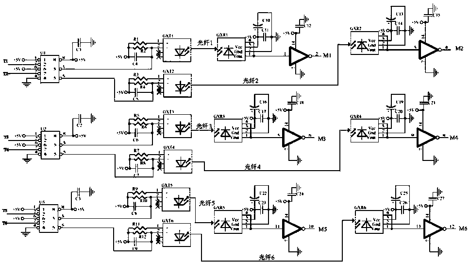
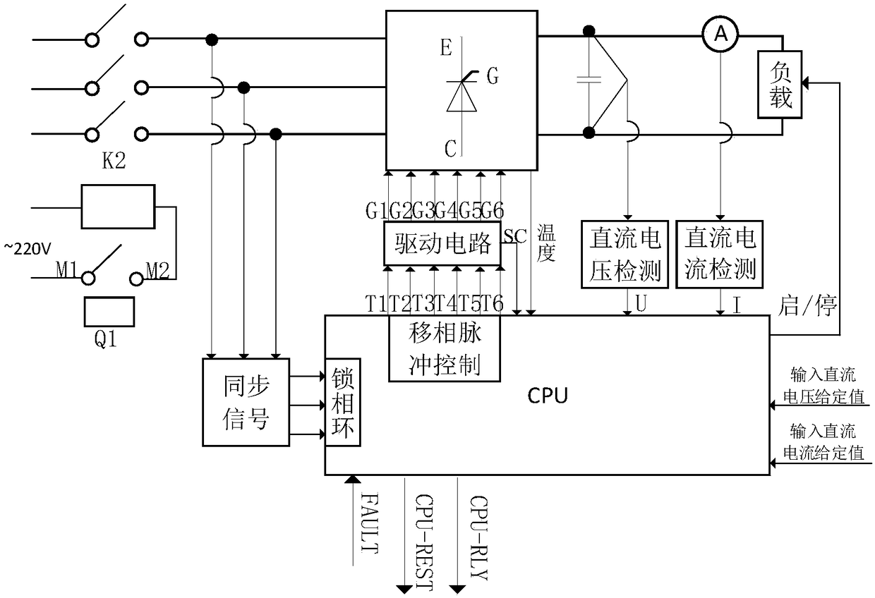
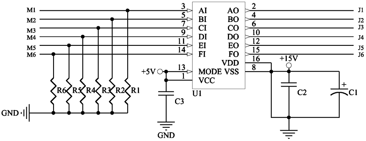
[0022] Such as figure 1 and combine figure 2 As shown in Figure 5, a self-protection high-efficiency phase-controlled rectification drive circuit includes a three-phase bridge phase-controlled rectification circuit, a CPU, a drive circuit, an intermediate relay, a main circuit contactor, a synchronous signal detection circuit, and a three-phase bridge temperature signal A detection circuit, a DC current detection circuit, a DC voltage detection circuit and a load, the CPU is connected to a three-phase bridge phase-controlled rectification circuit through a synchronous signal detection circuit, and the CPU is connected to a drive circuit, a DC current detection circuit and a DC voltage detection circuit A three-phase bridge-type phase-controlled re...


PUM


Abstract

The invention relates to the power electronics technology field and especially relates to a self-protecting high-efficiency phase-controlled rectification driving circuit. A CPU detects the phase andthe phase sequence of an input voltage through a synchronous signal detection circuit. The CPU is connected to a three-phase bridge-type phase-controlled rectification circuit through a driving circuit, a direct current detecting circuit, a direct voltage detecting circuit and a three-phase bridge temperature signal detecting circuit. A main circuit contactor is connected to the three-phase bridge-type phase-controlled rectification circuit. The temperature signal detecting circuit and an intermediate relay are connected to the main circuit contactor. A load is connected to a three-phase phase-controlled rectification circuit. In the invention, three-phase input voltage synchronization signals are collected to the CPU, and then a phase-locked loop technology is used to realize the synchronous locking of three-phase voltage phase; and a main-circuit three-phase bridge temperature signal, the fault signal of the driving circuit, the direct voltage signal on a direct current bus, and a direct current detection signal are collected and sent to the CPU.

Description

technical field [0001] The invention relates to the technical field of power electronics, in particular to a self-protection high-efficiency phase-controlled rectification drive circuit. Background technique [0002] Industries such as coal mines and rail transit have a strong dependence on rectifiers to obtain controllable or uncontrollable DC voltage. The conventional rectification link widely adopts diode uncontrolled rectification circuit and thyristor phase-controlled rectification circuit. With the rapid development of rail transit, the demand for megawatt-level high-power phase-controlled rectifiers in rail transit is increasing, and high-power, high-current, high-voltage thyristor devices have been widely used in the field of rail transit; With the continuous improvement of mining efficiency, high-power coal mining units and transportation equipment are constantly being used. The frequency conversion and speed regulation of these power equipment is achieved by recti...

Claims


Application Information

Patent Timeline
Patent Type & Authority Applications(China)
IPC IPC(8): H02M7/155H02M1/06H02H7/125
CPCH02M7/155H02H7/125H02H7/1255H02M1/06
Inventor 邓永红张全柱马红梅孙英娟雷旻薛伟宁赵立永陈海宇李圆红
Owner NORTH CHINA INST OF SCI & TECH
Why Eureka
Try Eureka