A missile-borne wide-beam high-gain antenna
A high-gain antenna, wide-beam technology, applied in antennas, antenna parts, electrical components, etc., can solve the problems of inability to adapt to antenna miniaturization, integrated anti-vibration, high reliability, and limited use range, and achieves a simple and reliable structure. , the effect of increasing antenna gain and improving reliability
Active Publication Date: 2015-09-23
AEROSPACE SCI & IND MICROELECTRONICS SYST INST CO LTD
View PDF0 Cites 4 Cited by
- Summary
- Abstract
- Description
- Claims
- Application Information
AI Technical Summary
Problems solved by technology
However, because the "antenna lens" technology needs to use a complex structure similar to the combination of optical lenses (used to realize the refraction of microwaves in the medium), its application range is greatly limited, and it cannot adapt to the bomb environment. The miniaturization, integration, and Anti-vibration and high reliability requirements
Searching Wanfang Data Resource Database, China Patent Information Database, some national defense patent internal bulletins, abstracts of aerospace and national defense science and technology reports, Internet resources, some professional journals published in China, and the catalog of US government reports, etc., no domestic and foreign publications have reported "" Missile-borne wide-beam high-gain antenna"
Method used
View moreImage
Smart ImageViewing Examples
Examples
example
Login to View More PUM
 Abstract
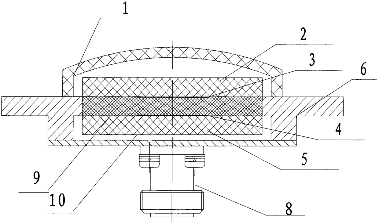
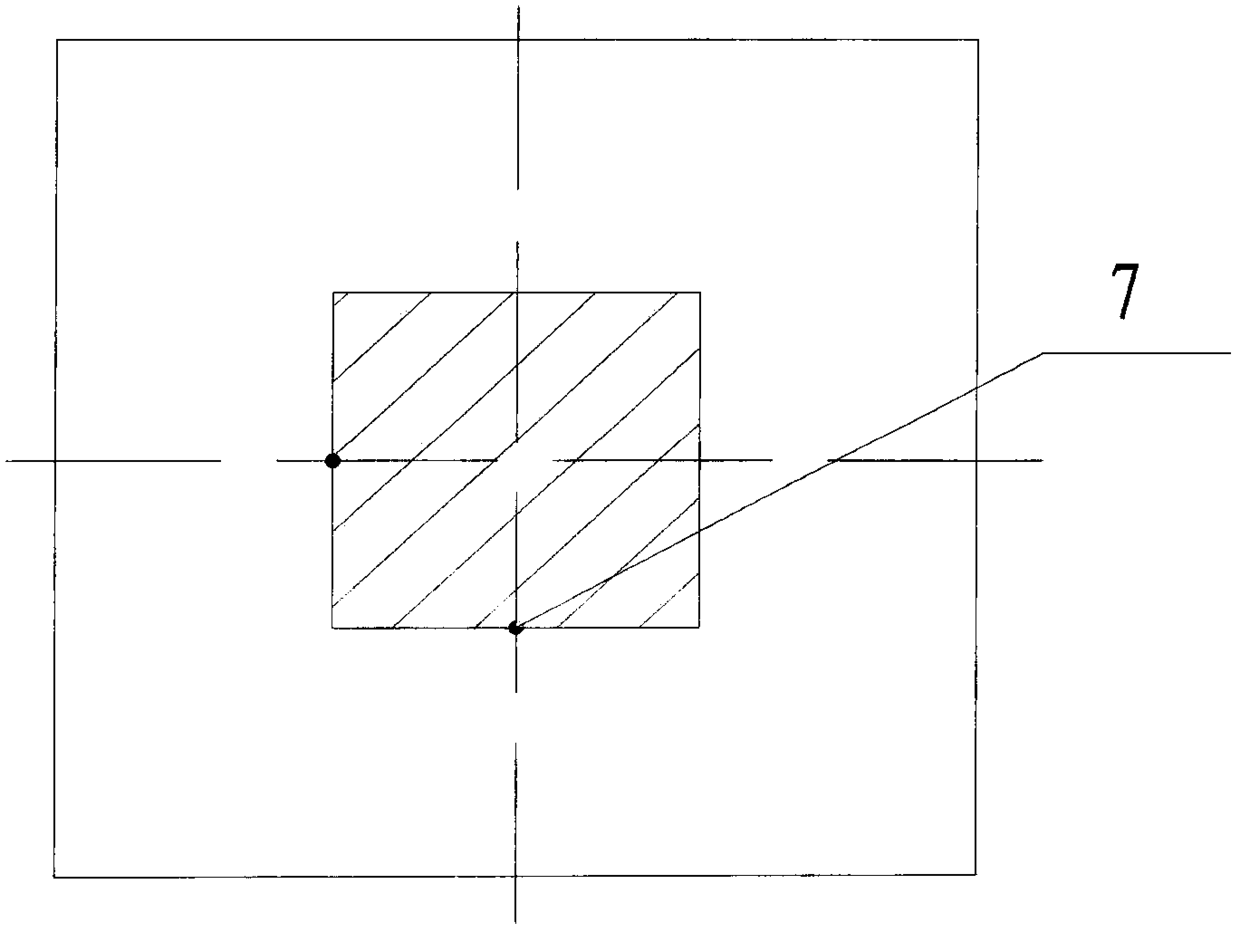
The invention discloses a bomb-loaded wide-beam high-gain antenna. Through the refraction effect of a dielectric plate, the antenna maintains a high gain in front and realizes a wide beam at the same time. The antenna structure is as follows: the radome contains a beam broadening dielectric plate and a radiation dielectric plate, the filling dielectric plate is located between the beam broadening dielectric plate and the radiation dielectric plate, and the side of the beam broadening dielectric plate close to the radiation dielectric plate is laid with a secondary radiation metal sheet; the radiation The side of the dielectric board close to the beam broadening dielectric board is laid with a primary radiation metal sheet, and the other side is covered with a metal floor; the primary radiation metal sheet contains a feed point; the dielectric boards of each layer are tightly pressed; the high-frequency socket is fixed at the bottom of the outer shell, The inner core of the high-frequency socket is connected with the feed point after being perforated inside the radiation medium plate. The invention improves on the basis of the "antenna lens" technology, makes the "lens" structure simple and reliable, and adapts to the requirements of the bomb use environment.
Description
technical field The invention belongs to radio antenna technology, in particular to a bomb-borne wide-beam high-gain antenna, Background technique Antennas are an important part of a radio system. In order to meet the special requirements of the radio communication on the missile, the antenna needs to have the characteristics of high gain and wide beam at the same time under the premise that the size and weight of the antenna meet the installation requirements. According to the traditional antenna theory and the principle of energy conservation, the realization of a wide beam of the antenna will inevitably lead to the decrease of the maximum gain of the antenna. On the contrary, to make the maximum gain of the antenna reach the limit will inevitably lead to the narrowing of the antenna beam. However, with the continuous advancement of technology in recent years, the method of using "antenna lens" technology to widen the beam of the antenna while maintaining the maximum gain...
Claims
Login to View More Application Information
Patent Timeline
 Patent Type & Authority Patents(China)
IPC IPC(8): H01Q1/00
Inventor 高帆白明顺杨道安商锋
Owner AEROSPACE SCI & IND MICROELECTRONICS SYST INST CO LTD
Features
- R&D
- Intellectual Property
- Life Sciences
- Materials
- Tech Scout
- Unparalleled Data Quality
- Higher Quality Content
- 60% Fewer Hallucinations
Learn More Browse by: Latest US Patents, China's latest patents, Technical Efficacy Thesaurus, Application Domain, Technology Topic, Popular Technical Reports.
© 2025 PatSnap. All rights reserved.Legal|Privacy policy|Modern Slavery Act Transparency Statement|Sitemap|About US| Contact US: help@patsnap.com


