Quick tool pouring ladle

A casting ladle and tooling technology, which is applied in the direction of manufacturing tools, metal processing equipment, and casting molten material containers, etc., can solve the problems of reduced slag blocking effect, complicated ladle building process, and large manpower and material resources, so as to achieve smooth discharge and reduce production Cost, the effect of reducing the waste of molten iron

Inactive Publication Date: 2018-11-16
广德亚太汽车智能制动系统有限公司
View PDF6 Cites 0 Cited by
  • Summary
  • Abstract
  • Description
  • Claims
  • Application Information

AI Technical Summary

Problems solved by technology

During the pouring process, the bridge-shaped curved surface at the bottom of the pouring ladle and the water inlet of the baffle are easily eroded, which will lead to problems such as unstable pouring and reduced slag blocking effect
[0003] In order to ensure product quality, the manufacturer uses an integrated packaging process, which is more complicated and consumes a lot of manpower and material resources each time.

Method used


Image

  • Quick tool pouring ladle
  • Quick tool pouring ladle
  • Quick tool pouring ladle

Examples


Embodiment Construction

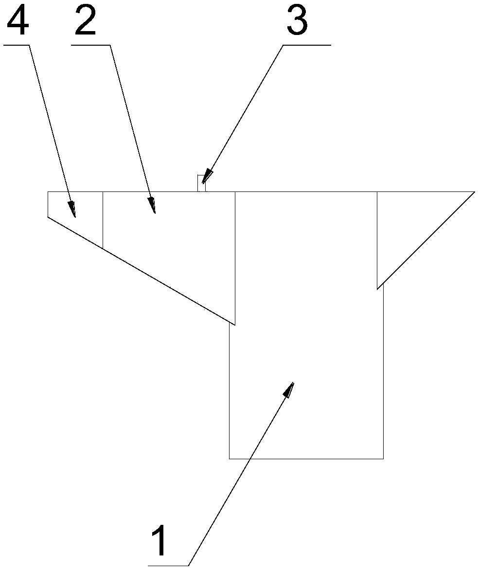
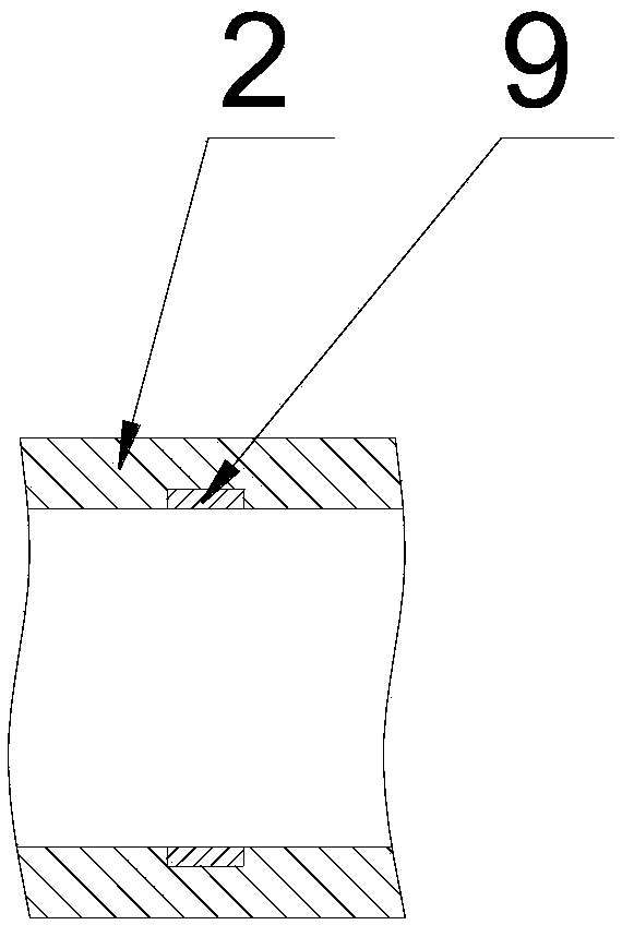
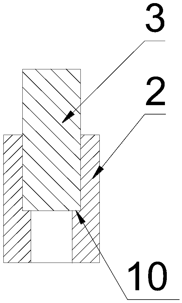
[0022] like Figure 1-6 as shown, figure 1 It is a structural schematic diagram of a quick tooling pouring ladle proposed by the present invention; figure 2 It is a top view of the end of the spout near the body of the quick tooling pouring bag proposed by the present invention; image 3 It is a schematic diagram of the connection structure between the spout and the slag retaining plate in the quick tooling pouring ladle proposed by the present invention; Figure 4 It is a top view of the discharge end of the spout in the quick tooling pouring bag proposed by the present invention; Figure 5 It is a top view of the connection structure between the spout and the movable spout in the quick tooling pouring ladle proposed by the present invention; Image 6 It is a front view of the connection structure between the spout and the movable spout in the rapid tooling pouring ladle proposed by the present invention.

[0023] refer to Figure 1-6 , a rapid tooling pouring ladle pro...


PUM


Abstract

The invention discloses a quick tool pouring ladle. The quick tool pouring ladle comprises a body, a ladle mouth, a slag retaining plate and a movable ladle mouth, wherein the slag retaining plate andthe movable ladle mouth are detachably arranged on the ladle mouth; the ladle mouth comprises a base plate and a side plate; the ladle mouth is arranged at the front end of the body; one end, close to the body, of the ladle mouth is provided with a first accommodating groove; the slag retaining plate is inserted into the first accommodating groove in a matching manner; a discharging opening for discharging liquid iron is formed between the bottom of the slag retaining plate and the base plate; one end, far away from the body, of the ladle mouth is a discharging end; the discharging end of theladle mouth is provided with a second accommodating groove; the movable ladle mouth comprises a first base plate and a first side plate; the movable ladle mouth is inserted into the second accommodating groove in a matching manner; and the movable ladle mouth and the ladle mouth are fixed by using a locating pin. According to the quick tool pouring ladle disclosed by the invention, the service life of the pouring ladle is prolonged and the pouring quality is stabilized by replacing a tool; a fetal membrane manufacturing process of the pouring ladle is simplified; and labor and materials are saved.

Description

technical field [0001] The invention relates to the field of molten iron pouring, in particular to a quick tooling pouring ladle. Background technique [0002] A pouring ladle is a tool used for pouring molten iron. During the pouring process, the curved surface of the bridge at the bottom of the pouring ladle and the water inlet part of the baffle are easily eroded, which will lead to problems such as unstable pouring and reduced slag blocking effect. [0003] In order to ensure product quality, the manufacturer uses an integrated packaging process, which is relatively complicated and consumes huge manpower and material resources each time. [0004] Therefore, how to improve the service life and use effect of the casting ladle is an urgent problem for foundry enterprises to solve. Contents of the invention [0005] In order to solve the technical problems existing in the background technology, the present invention proposes a quick tooling pouring ladle. [0006] A qui...

Claims


Application Information

Patent Timeline
Patent Type & Authority Applications(China)
IPC IPC(8): B22D41/04
CPCB22D41/04
Inventor 魏明强高元
Owner 广德亚太汽车智能制动系统有限公司
Why Eureka
Try Eureka