
Machining device for machine

A processing device and mechanical technology, applied in the direction of positioning device, metal processing equipment, metal processing machinery parts, etc., can solve the problems of affecting the heating effect, cumbersome operation, high processing temperature, etc., and achieve the advantages of easy processing, convenient operation and avoiding shaking Effect

Inactive Publication Date: 2018-11-16
熊飞燕
View PDF0 Cites 6 Cited by
  • Summary
  • Abstract
  • Description
  • Claims
  • Application Information

AI Technical Summary

Problems solved by technology

[0005] Aiming at the deficiencies of the prior art, the present invention provides a processing device for machinery, which solves the problem that a lot of heat will be generated during processing. Since the generated heat cannot be dissipated for a while, it is easy to cause the processing temperature to be too high and affect the heating effect , and some processed mechanical tools need to be cooled before proceeding to the next step of processing, and the operation is more cumbersome

Method used


Image

  • Machining device for machine
  • Machining device for machine
  • Machining device for machine

Examples


Embodiment approach 1

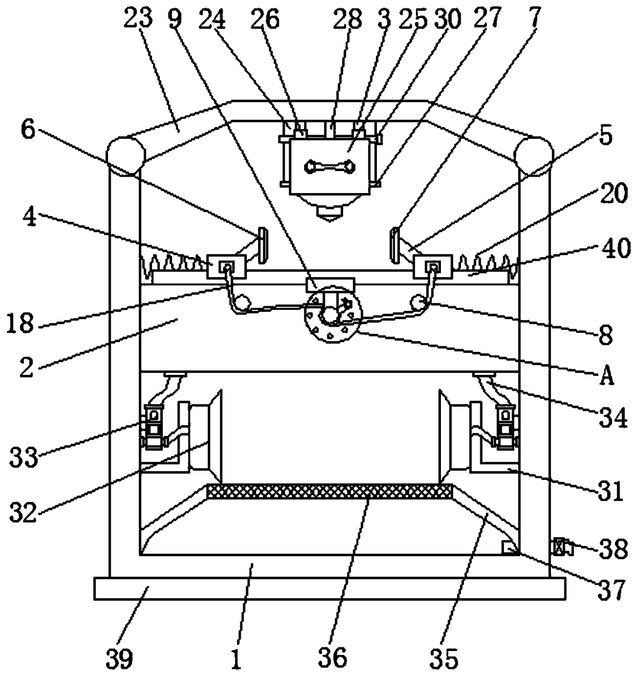
[0032] Implementation method 1, please refer to Figure 1-8, a processing device for machinery, comprising a housing 1, the top of the housing 1 is fixedly connected with a box cover 23, the bottom of the box cover 23 is fixedly connected with a connecting plate 24, and the front of the connecting plate 24 is fixedly connected with a limiting plate 28, sliding The inner surfaces of the block 26 and the limiting plate 28 are all provided with limiting holes 29, the inner surfaces of the limiting holes 29 are movably connected with the limiting rods 30, and the left and right sides of the connecting plate 24 fronts are all fixedly connected with the second slide rail 3, Utilize the cooperation between the second slide rail 3 and the sliding block 26 to make the processing device 25 slide up and down on the second slide rail 3, and then adjust the position of the processing device 25, and then utilize the gap between the stop bar 30 and the stop hole 29 to The cooperation between...

Embodiment approach 2

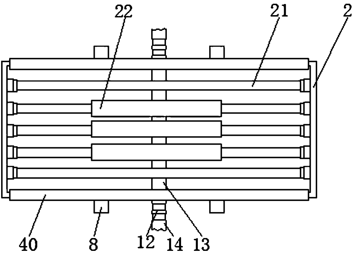
[0033] Implementation mode two, please refer to Figure 1-8 , a processing device for machinery, comprising a casing (1), characterized in that: the inside of the casing (1) is fixedly connected with a cooling box (2), and the front and rear sides of the cooling box (2) are fixed The first slide rails (40) are connected, the two first slide rails (40) are slidably connected with slide plates (4), and the opposite sides of the two slide plates (4) are fixedly connected with support plates (5), and the side of the support plate (5) away from the sliding plate (4) is fixedly connected with a splint (6), and one side of the splint (6) is fixedly connected with a buffer plate (7), and the cooling box ( 2) The front and rear sides are rotatably connected with guide posts (8), the front and rear sides of the cooling box (2) are fixedly connected with fixed blocks (9), and the bottom of the fixed block (9) is fixedly connected with connecting Rod (10), the bottom end of the connectin...

Embodiment approach 3

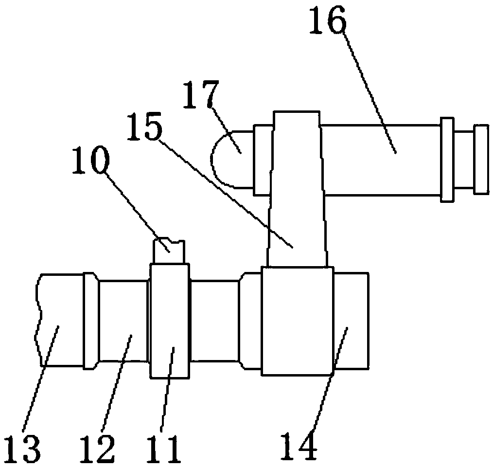
[0034] Implementation Mode 3, please refer to Figure 1-8 , a processing device for machinery, one end of the outer surface of the winding post (12) is fixedly connected with a rotating rod (14), and the outer surface of the rotating rod (14) is fixedly connected with a rocker (15), A handle (16) is fixedly connected to the inner surface of the rocker (15), and the inner surface of the handle (16) is slidably connected to a limiting column (17).


PUM


Abstract

The invention discloses a machining device for a machine. The machining device comprises a shell. The interior of the shell is fixedly connected with a cooling box. The front side and the rear side ofthe cooling box are fixedly connected with first sliding rails. The outer surfaces of the two first sliding rails are in sliding connection with sliding plates. The opposite sides of the two slidingplates are fixedly connected with supporting plates. The side, away from the corresponding sliding plate, of each supporting plate is fixedly connected with a clamp plate. One side of each clamp plateis fixedly connected with a buffer plate. The invention relates to the technical field of machines. According to the machining device for the machine, the cooling box is utilized for absorbing heat generated by machining when the machining device carries out machining, and the situation that the machining effect is influenced due to the fact that the machining environment is too high is avoided;and meanwhile, through cooperation of a wire winding column and a pull rope, the sliding plates can be driven to move on the first sliding rails, then the clamp plates are driven to clamp a machined mechanical tool, the machining device can machine the machined mechanical tool conveniently, the machined tool is prevented from offsetting, and machining is more precise.

Description

technical field [0001] The invention relates to the technical field of machinery, in particular to a processing device for machinery. Background technique [0002] Machinery refers to the general term of machines and mechanisms. Machinery is a tool device that can help people reduce the difficulty of work or save labor. Items such as chopsticks, brooms, and tweezers can all be called machines. They are simple machines. A complex machine is composed of two or more simple machines. These more complex machines are usually called machines. From the point of view of structure and motion, there is no difference between a mechanism and a machine, and it is generally called a machine. Mechanical engineering is based on the relevant natural science and technical science as the theoretical basis, combined with the technical experience accumulated in production practice, to study and solve the theoretical and practical problems in the development, design, manufacture, installation, u...

Claims


Application Information

Patent Timeline
Patent Type & Authority Applications(China)
IPC IPC(8): B23Q1/01B23Q3/06
CPCB23Q3/06B23Q1/015
Inventor 不公告发明人
Owner 熊飞燕
Learn More