
Roller cutting machining equipment

A cutting and drum technology, applied in metal processing and other directions, can solve the problems of difficult quality assurance, occupying workshop space, uneven end faces, etc., and achieves the effect of compact structure and small space occupation.

Inactive Publication Date: 2018-11-16
李卫
View PDF5 Cites 2 Cited by
  • Summary
  • Abstract
  • Description
  • Claims
  • Application Information

AI Technical Summary

Problems solved by technology

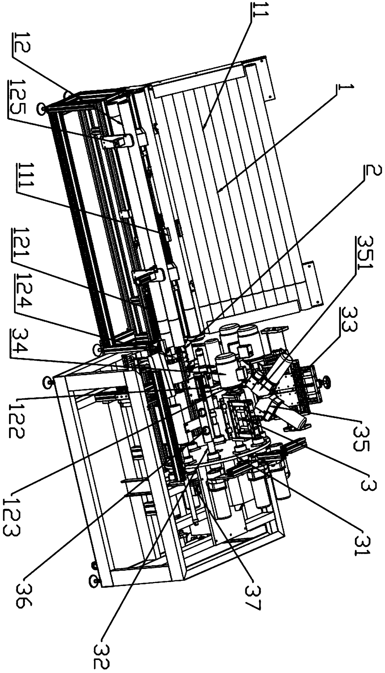
[0002] The roller brush is a product that must be used for decoration and plastering. The roller on the roller brush is a plastic cylinder with a circle of bristles on the outer coat. When producing the roller, a long plastic tube is used to cover the bristles, and then cut. Before cutting, it is necessary to comb and cut the bristles of the drum, so as to ensure the quality of the product. However, the existing equipment has cumbersome processing steps and many processes, resulting in a large equipment volume and occupying the workshop space. At the same time, the current production equipment is all The end surface of the drum is not cut, resulting in uneven end surface after the drum is produced, and the quality is difficult to guarantee

Method used


Image

  • Roller cutting machining equipment
  • Roller cutting machining equipment
  • Roller cutting machining equipment

Examples


Embodiment Construction

[0022] The technical solutions of the present invention will be described below in conjunction with the accompanying drawings and embodiments.

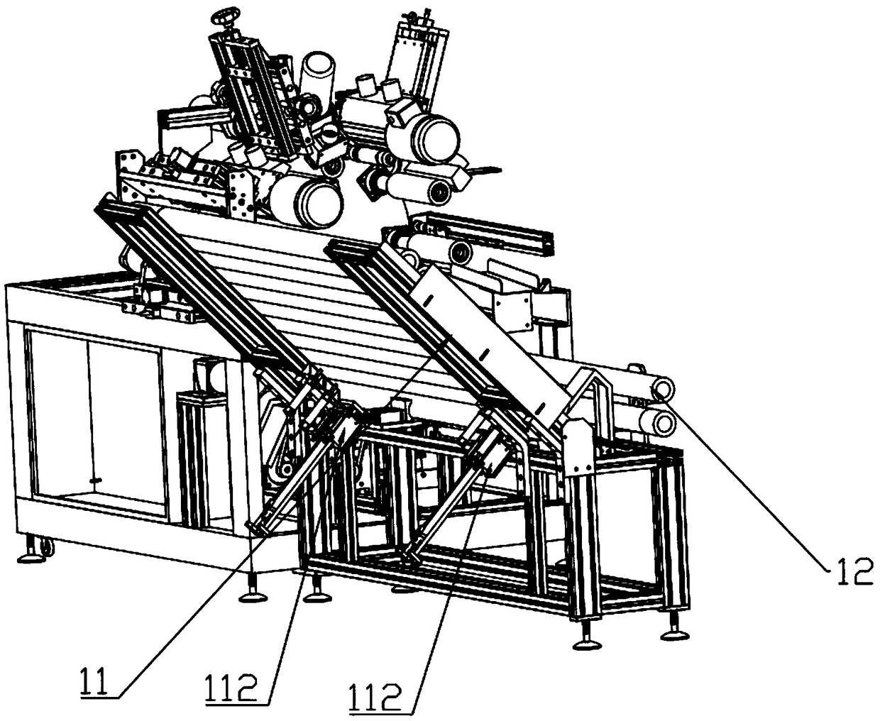
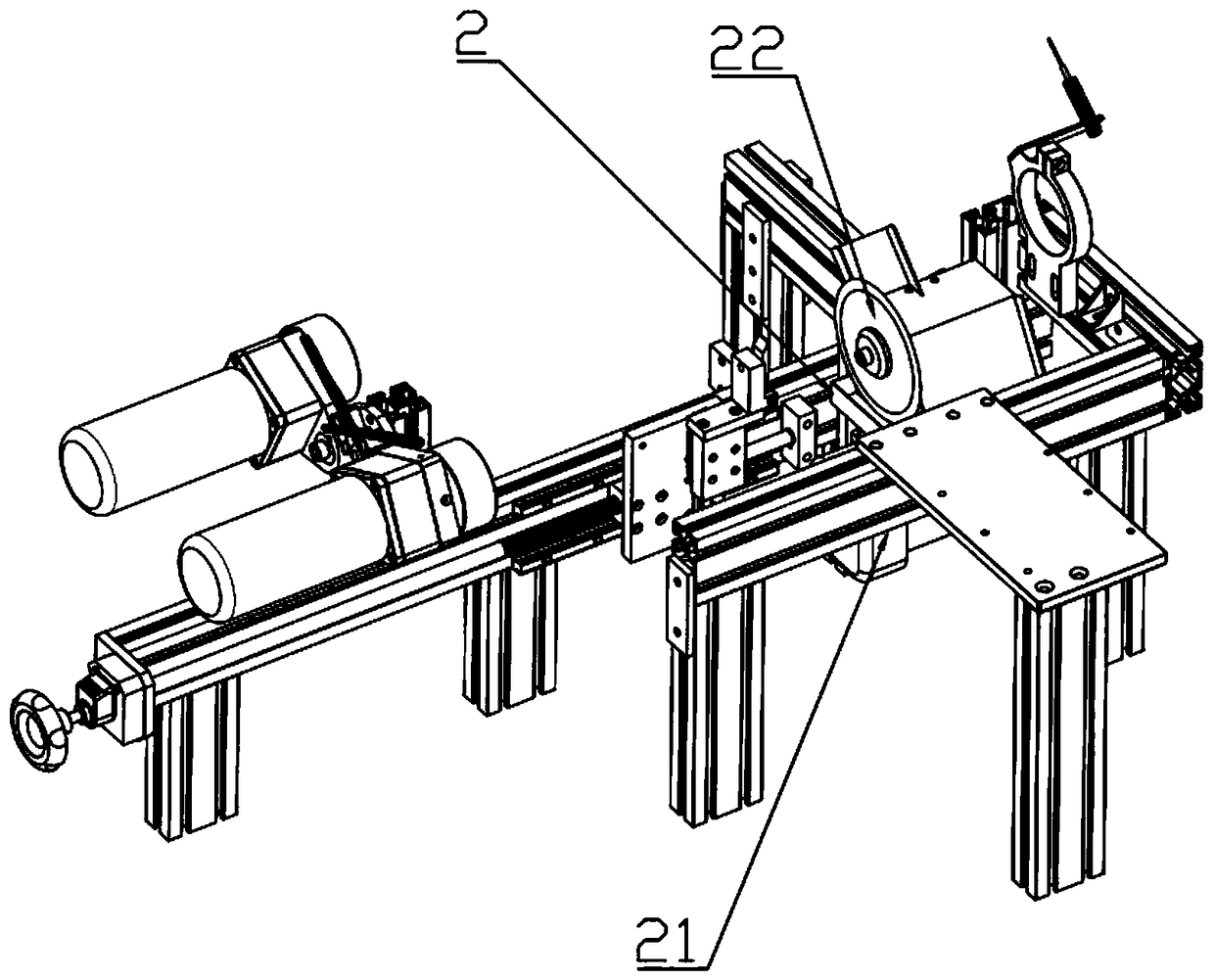
[0023] Such as Figure 1 to Figure 4 As shown, a kind of drum cutting processing equipment according to the present invention includes a discharge rack 1, a surplus material cutting mechanism 2 and a peripheral processing mechanism 3. The peripheral processing mechanism 3 includes a turntable 31 driven by a motor to rotate, The turntable 31 is equipped with a plurality of rotating shafts 32 driven by motors in the circumferential direction, and the rotating shafts 32 are used to trap the drum. A combing mechanism 33, a shearing mechanism 34 and a chamfering mechanism 35 are respectively installed on one side of the plurality of rotating shafts 32. , the combing mechanism 33 is used to comb the drum, the shearing mechanism 34 cuts the hair of the drum short, and the chamfering mechanism 35 is used to chamfer the two ends of the drum; w...


PUM


Abstract

The invention provides roller cutting machining equipment. The problems that existing equipment is large in structure and occupies space are solved. The roller cutting machining equipment comprises afeeding rack, an excessive material cutting mechanism and a circumferential machining mechanism. The circumferential machining mechanism comprises a rotating disc driven by a motor to rotate. Multiplerotating shafts driven by the motor are arranged in the circumferential direction of the rotating disc and used for sleeving rollers. A carding mechanism, a shearing mechanism and a chamfering mechanism are mounted beside the multiple rotating shafts. The feeding rack comprises a first feeding groove and a second feeding groove. A pushing air cylinder is further arranged on the first feeding groove and used for pushing the rollers into the second feeding groove from the first feeding groove. The excessive material cutting mechanism is arranged at the tail end of the first feeding groove. According to the roller cutting machining equipment, excessive material cutting is carried out, and the end faces of finished rollers can be level; disc type machining is achieved, the structure is compact, and the occupied space is small; and the first feeding groove and the second feeding groove are arranged and used for material preparing and feeding, and the material preparing time is shortened.

Description

technical field [0001] The invention relates to the technical field of roller brushes, in particular to a roller cutting and processing equipment. Background technique [0002] The roller brush is a product that must be used for decoration and plastering. The roller on the roller brush is a plastic cylinder with a circle of bristles on the outer coat. When producing the roller, a long plastic tube is used to cover the bristles, and then cut. Before cutting, it is necessary to comb and cut the bristles of the drum, so as to ensure the quality of the product. However, the existing equipment has cumbersome processing steps and many processes, resulting in a large equipment volume and occupying the workshop space. At the same time, the current production equipment is all The remaining material on the end face of the drum is not cut, resulting in uneven end faces after the drum is produced, making it difficult to guarantee the quality. Contents of the invention [0003] In vie...

Claims


Application Information

Patent Timeline
IPC IPC(8): B26D1/18B26D5/08B26D5/04B26D7/02B26D7/08B26D7/06B26D7/32
CPCB26D1/18B26D5/04B26D5/08B26D7/02B26D7/0608B26D7/08B26D7/32B26D2007/013
Inventor 李卫
Owner 李卫
Learn More