Casting valve and coating device with same

A coating device and casting technology, applied in the field of casting valve and coating device, can solve the problems of unstable casting of the casting valve, improve the uniformity of coating, reduce the generation of droplets, and achieve strong continuity. Effect

Pending Publication Date: 2018-11-16
温岭市聚氟科技有限公司
View PDF1 Cites 2 Cited by
  • Summary
  • Abstract
  • Description
  • Claims
  • Application Information

AI Technical Summary

Problems solved by technology

[0006] The object of the present invention is to provide a casting valve, which solves the problem of unstable casting of the casting valve, and achieves the effect of stable casting and uniform coating

Method used


Image

  • Casting valve and coating device with same
  • Casting valve and coating device with same
  • Casting valve and coating device with same

Examples


Embodiment 1

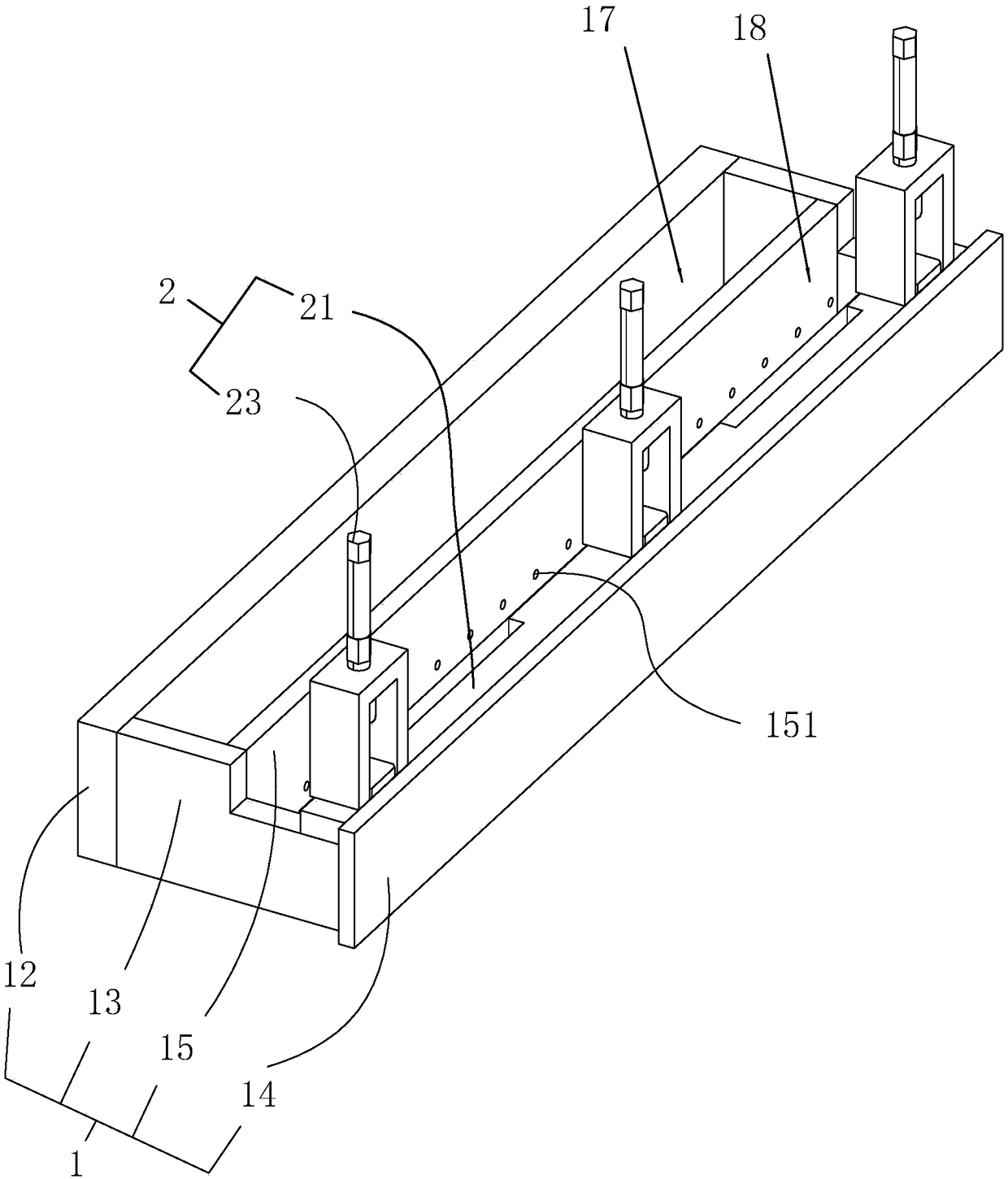
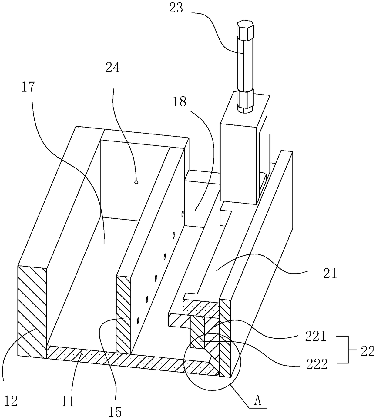
[0040] Embodiment 1: casting valve and the coating device with the casting valve, such as figure 1 and figure 2 As shown, it includes a substrate 1 and a valve 2 , and the valve 2 controls the opening and closing of the liquid outlet 16 of the substrate 1 .

[0041] The base 1 includes a bottom plate 11, a vertical plate 12, a side plate 13 and an end plate 14 that mutually surround a chamber with an upward opening, and also includes a partition that stands in the chamber and divides the chamber into a liquid storage tank 17 and a casting tank 18. The plate 15 and the separator 15 are parallel to the vertical plate 12 and the end plate 14 , and the end plate 14 is located on the side of the casting tank 18 away from the liquid storage tank 17 .

[0042] The upper opening of the liquid storage tank 17 is the liquid inlet, and the lower part of the partition plate 15 is arranged with a plurality of connecting holes 151 connecting the liquid storage tank 17 and the casting tank...

Embodiment 2

[0046] Embodiment 2: as Figure 4 As shown, the difference from Embodiment 1 is that the valve 2 also includes a second valve plate 25 that slides along the surface of the partition 15 to cover the connecting hole 151 and is fixed on the base 1 to drive the second valve plate 25 moves the second push cylinder 26 .

[0047] The second valve plate 25 and the first valve plate 22 both can finish opening and closing action simultaneously, also can finish opening and closing action respectively; The amount of solution can always be kept at a constant liquid level at the bottom, and can also be kept at a constant flow rate; when it is respectively opened and closed, quantitative coating can be completed, that is, when the liquid outlet 16 is closed, the solution begins to accumulate in the casting tank 18, Then, the contact holes 151 are closed during coating.

Embodiment 3

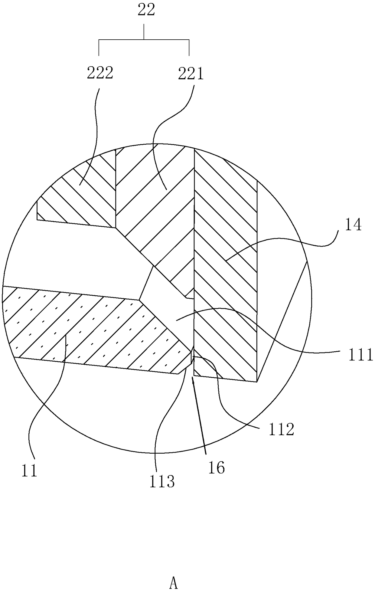
[0048] Embodiment 3: as Figure 5 As shown, the difference from Embodiment 1 or 2 is that the end plate 14 and the bottom plate 11 are abutted and closed, the end plate 14 is lower than the other side walls of other casting grooves 18, and the ends of the end plate 14 are respectively provided with Inclined inner guide surface and outer guide surface; when closed, the end of the first valve plate 22 abuts against the inner guide surface and the outer guide surface at the same time.


PUM


Abstract

The invention discloses a casting valve and a coating device with the same, and relates to the field of casting process firming. The casting valve comprises a base body and is characterized in that the base body is provided with a liquid storage tank and a casting tank which are adjacently arranged and separated by a partition plate, and a valve for controlling the liquid outlet of the casting tank to be opened and closed is also arranged on the base body; and a plurality of connecting holes communicating with the liquid storage tank and the casting tank are formed in the lower part of the partition plate in the horizontal direction, and the liquid inlet of the liquid storage tank is located at the upper part of the liquid storage tank. The casting valve and the coating device with the same has the advantages that the continuity is high, the firming efficiency is high, the coating uniformity is good, and the filming thickness is small.

Description

technical field [0001] The invention relates to the field of casting film production, in particular to a casting valve and a coating device equipped with the casting valve. Background technique [0002] In electronic components, ceramic insulating substrates, ceramic substrates, dielectric layers, protective layers, ion diaphragms, and especially ion membranes for fuel cells are usually prepared by tape casting: that is, the raw materials are first made into slurry, and after treatment Finally, it is cast on a tape casting machine to form a green film, and then dried and fired to shape. [0003] Casting valve is the mechanism used to coat the solution on the casting machine, and it is also an important mechanism to determine the quality of film formation. Existing cast valves generally use overflow cast valves. [0004] For example, the Chinese patent with the authorized announcement number CN2816041Y discloses an overflow casting device, which includes a casting tank, a r...

Claims


Application Information

Patent Timeline
Patent Type & Authority Applications(China)
IPC IPC(8): B29C41/12B29C41/34B29C41/52B29L7/00
CPCB29C41/12B29C41/34B29C41/52B29L2007/00
Inventor 朱沛林朱沛明
Owner 温岭市聚氟科技有限公司
Why Eureka
Try Eureka