
Front edge paper feed portion for corrugated paper printing equipment and drive device of front edge paper feed portion

A technology of printing equipment and driving device, which is applied to the general parts of printing machinery, printing, printing machines, etc., can solve the problems of inability to start and stop quickly, and achieve the effects of inability to start and stop quickly, small vibration, and stable operation of equipment

Active Publication Date: 2018-11-16
GUANGZHOU KESHENGLONG CARTON PACKING MACHINE
View PDF7 Cites 2 Cited by
  • Summary
  • Abstract
  • Description
  • Claims
  • Application Information

AI Technical Summary

Problems solved by technology

[0004] The object of the present invention is to overcome the deficiencies of the prior art, and provide a driving device for the leading edge paper feeding part of corrugated paper printing equipment with a simplified structure. start-stop problem

Method used


Image

  • Front edge paper feed portion for corrugated paper printing equipment and drive device of front edge paper feed portion
  • Front edge paper feed portion for corrugated paper printing equipment and drive device of front edge paper feed portion
  • Front edge paper feed portion for corrugated paper printing equipment and drive device of front edge paper feed portion

Examples


Embodiment 1

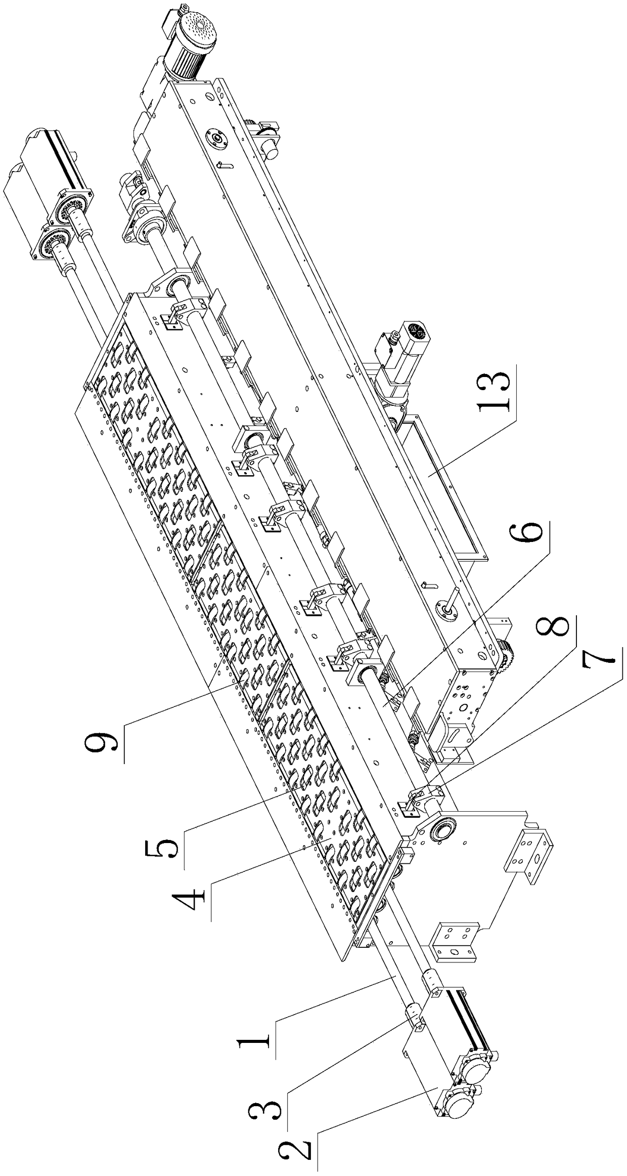
[0042] In this embodiment, a driving device for the leading edge paper feeding part of corrugated paper printing equipment includes a servo motor, a coupling and a main control device, such as image 3 or Figure 5 As shown, each paper feeding shaft 1 in the leading edge paper feeding part is correspondingly equipped with a servo motor 2, and the output shaft of each servo motor is connected to a paper feeding shaft through a coupling 3, and each servo motor is connected to the main shaft respectively. control device connection;

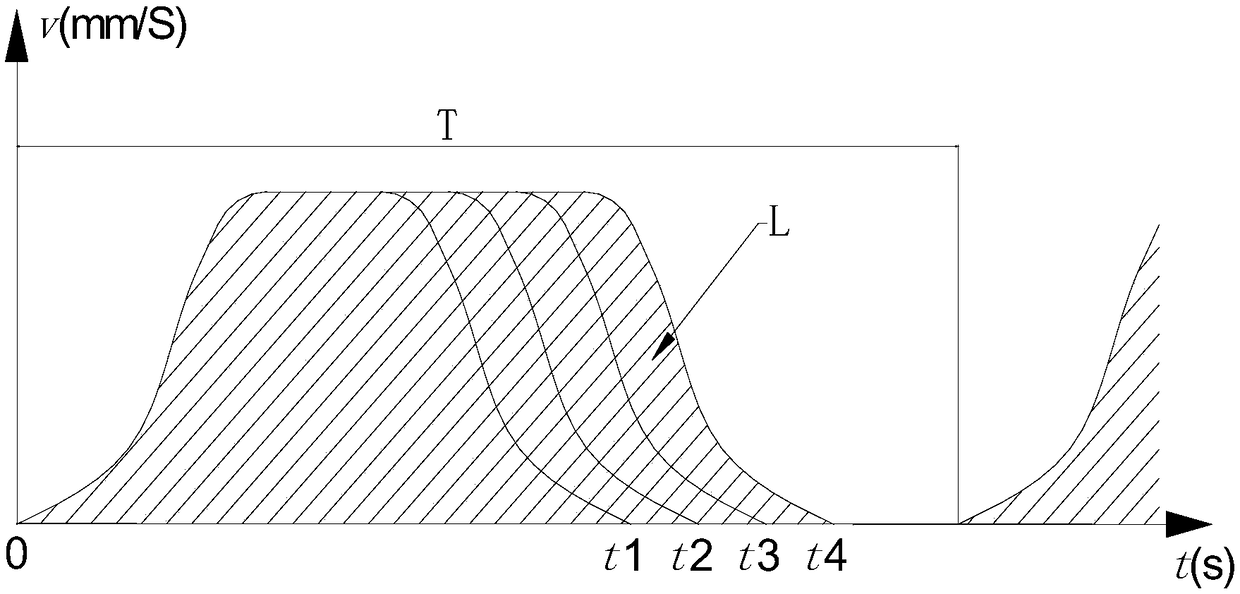
[0043] Such as figure 1 As shown, the main control device is equipped with a time signal synchronization monitoring module, an information input module, a main control module, a drive circuit and an encoder. The signal synchronization monitoring module and the information input module are connected to the main control module respectively, and the main control module passes through the drive circuit Connect each servo motor, and each servo motor is ...

Embodiment 2

[0054] In this embodiment, a leading edge paper feeding unit for corrugated printing equipment with the driving device described in Embodiment 1, such as image 3 As shown, it includes a paper feeding platform and a lifting mechanism. The top surface of the paper feeding platform is a lifting plate 4, and wheel holes 5 are distributed on the lifting plate. The bottom of the lifting plate is connected with the lifting mechanism; A plurality of paper feed shafts 1, each paper feed shaft is provided with a plurality of paper feed wheels 9, each paper feed shaft is arranged under the lifting plate in parallel, and each paper feeding wheel is correspondingly located in a wheel hole; Driven by the lifting mechanism, the lifting movement is carried out; one end of each paper feeding shaft is independently provided with a servo motor 2, and the servo motor is connected to the paper feeding shaft through a coupling 3.

[0055] Lifting plate lifting mechanism includes swinging main shaf...

Embodiment 3

[0058] In this embodiment, a leading edge paper feeding unit for corrugated printing equipment with the driving device described in Embodiment 1, such as Figure 5 or Image 6As shown, it includes a paper feeding platform and a paper supporting mechanism. The paper supporting mechanism is a swing lifting structure, including a push rod 14, a fence rod 15, a swing connecting rod 16, a transmission block 17 and a swing main shaft 6. The swing main shaft is set on the paper feeding On the outside of the platform, the transmission block is fixedly connected to the swing spindle, one end of the swing link is hinged to the drive block, the other end of the swing link is hinged to the ejector rod, the other end of the ejector rod is hinged to the paper feeding platform, and multiple fence bars are distributed on the ejector rod On the surface of the paper feeding platform, there are multiple fence holes, and each fence rod is correspondingly located in a fence hole and moves up and d...


PUM


Abstract

The invention discloses a front edge paper feed portion of corrugated paper printing equipment and a drive device of the front edge paper feed portion. The drive device comprises servo motors, couplings and a master control device. Each paper feed shaft in the front edge paper feed portion is correspondingly provided with the corresponding servo motor, each servo motor is connected with the corresponding paper feed shaft through the corresponding coupling, and the servo motors are connected with the master control device. A time signal synchronous monitoring module, an information input module, a master control module, a drive loop and an encoder are arranged in the master control device. The front edge paper feed portion is provided with the drive device and comprises a paper feed platform and a lifting plate lifting mechanism. A lifting plate on the paper feed platform is driven through the lifting plate lifting mechanism to do lifting motion, and the paper feed shafts are driven bythe servo motors to complete paper feed. Or, the front edge paper feed portion comprises the paper feed platform and a paper supporting mechanism, and through lifting motion of the paper supporting mechanism, the paper feed shafts are driven by the servo motors to complete paper feed. According to the front edge paper feed portion of the corrugated paper printing equipment and the drive device ofthe front edge paper feed portion, the paper feed speed can be greatly improved, and the problem that a traditional paper feed device cannot be started or stopped rapidly is effectively solved.

Description

technical field [0001] The invention relates to the field of corrugated paper processing equipment, in particular to a leading edge paper feeding part and a driving device thereof for corrugated paper printing equipment. Background technique [0002] In corrugated paper printing and processing equipment, during a paper feeding cycle of the front edge feeding part, the motor suddenly accelerates from a stop state to a high-speed rotation state until it completes sending out the cardboard at the bottom of the stack, which requires rapid braking. In the current equipment, multiple paper feed rollers are generally controlled separately by a single motor. In this case, if the speed suddenly increases, the motor will not be able to meet the speed required by each paper feed roller. During the process, the engagement and disengagement of the clutch and the braking of each row of paper feed rollers take a certain amount of time. However, in order to improve the printing efficiency ...

Claims


Application Information

Patent Timeline
IPC IPC(8): B41F21/00
CPCB41F21/00B65H3/0692B65H3/063B65H3/0607
Inventor 何国胜陈永生庞少辉
Owner GUANGZHOU KESHENGLONG CARTON PACKING MACHINE
Learn More