Vacuum adsorption front edge paper feed unit in carton making linkage machine

A paper feeding unit and vacuum adsorption technology, applied in paper/cardboard containers, container manufacturing machinery, containers, etc., can solve the problems of high price, slow paper feeding, cardboard feeding, etc., and achieve low manufacturing cost and paper feeding speed. Quick, easy-to-understand effects

Inactive Publication Date: 2011-04-06
黄锋
View PDF0 Cites 0 Cited by
  • Summary
  • Abstract
  • Description
  • Claims
  • Application Information

AI Technical Summary

Problems solved by technology

The problem with this paper feeding unit is that when the cardboard is not flat enough, the paper pushing mechanism often cannot send the cardboard into the gap between the paper feeding rollers, which affects the normal operation of the linkage machine; the second is that the paper feeding speed is too slow and the efficiency is low
The American company has a linkage machine for the vacuum adsorption leading edge paper feeding unit, but due to its complex structure, high manufacturing cost, and the need to pay patent royalties, the price is very high

Method used


Image

  • Vacuum adsorption front edge paper feed unit in carton making linkage machine
  • Vacuum adsorption front edge paper feed unit in carton making linkage machine
  • Vacuum adsorption front edge paper feed unit in carton making linkage machine

Examples


Embodiment 1

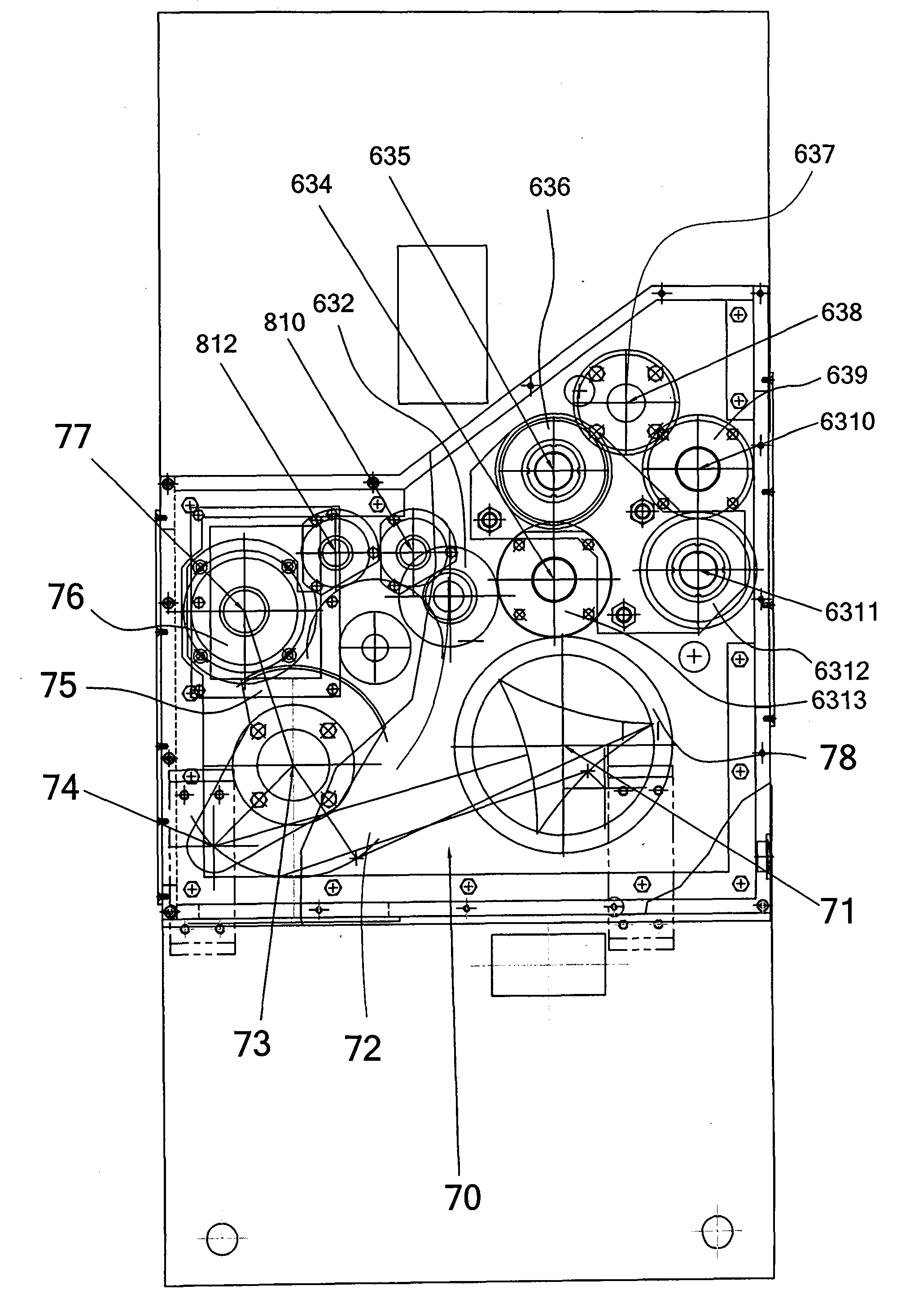
[0046] Embodiment 1, referring to Fig. 1-Fig. 3. The paper feed unit of the present embodiment comprises the machine table 50 of the paper feed unit, the manipulation control box 10, a main motor 61, the paper feed roller group 20 and the suction device 30, and also includes:

[0047] A transmission mechanism 60 that drives the paper feed roller (see Figure 4 ), which includes:

[0048] The pulley deceleration mechanism driven by the main motor 61, the deceleration mechanism includes a small pulley 65 mounted on the output shaft end of the main motor, a large pulley 66 and a transmission belt 62 mounted on the front end of the first drive shaft 67 described below (see Figure 5) ;

[0049] One first power transmission shaft 67, the rear end of this first power transmission shaft 67 is equipped with jaw coupling 672, links with the second power transmission shaft of the printing unit behind by this jaw coupling, this first A first synchronous pulley 671 is installed near the ...

Embodiment 2

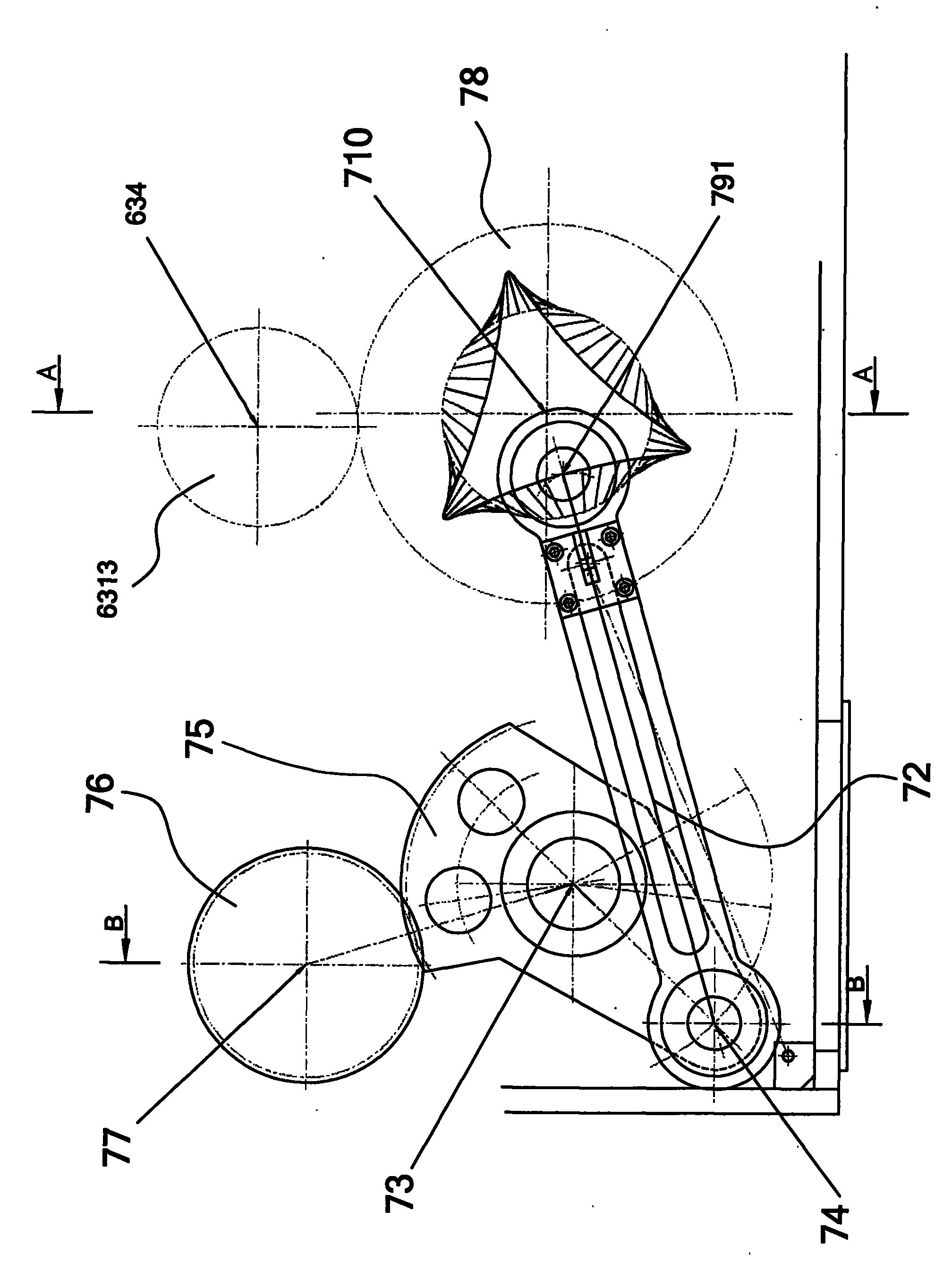
[0063] Embodiment 2, see again Figure 17 and Figure 12. This embodiment is based on the above-mentioned embodiment. In the said paper feeding belt reciprocating mechanism 70, it also includes a flange plate 711 with a boss. On the edge of the flange plate 711, 3 or 4 arc-shaped long slots 7111, the central angle a of each arc-shaped long slot 7111 is between 25°-35° (see Figure 16), the inner hole of the flange 711 is connected with the above-mentioned sleeve 713 through the key The tail parts are connected together, and 3-4 screw holes 7112 are also provided on its rim, and it is fixed on the right side plate 41 with screws. When the screw is loosened and the position of the arc-shaped long groove 7111 on the edge of the flange 711 is adjusted, the position of the large ring gear 710 relative to the pinion 714 can be adjusted accordingly, thereby adjusting the back and forth of the paper feeding belt 723 The swing angle is the central angle a.

Embodiment 3

[0064] Embodiment 3, refer to Fig. 16 again. In this embodiment, on the basis of the above two embodiments, the central angle a between the first fixed point 720 and the second fixed point 724 of a section of the part where the paper feeding belt 723 is wrapped on the large paper feeding pulley 719 The adjustment is 153°. Practice has proved that the central angle is the best.

[0065] Before work, the cardboard 90 is stacked on the machine platform 50 of the paper feeding unit, and the bottom of the machine platform is the suction box 40 . Then, start the motor of the main motor 61 and the air suction device, and the suction force of the air suction box 40 will firmly adsorb the lowermost cardboard 90 on the machine table. The main motor 61 drives the four paper feed rollers 21-24 to rotate through the above-mentioned transmission mechanism 60 for driving the paper feed rollers. Cams 811 and 813 rotate. When the cam lifted the lowermost cardboard 90 and was slightly highe...


PUM


Abstract

The invention discloses a vacuum absorption front edge paper feed unit in a carton making linkage machine and aims at overcoming the disadvantage of easy occurrence of unsmooth paper feed in a back-push paper feed of the prior art. The vacuum absorption front edge paper feed unit comprises a machine table of the paper feed unit, a manipulation and control box, a main motor, a paper feed roller group and an air suction device. The vacuum absorption front edge paper feed unit is characterized in that the vacuum absorption front edge paper feed unit further comprises a drive mechanism for drivingpaper feed rollers, a paper feed belt reciprocating motion mechanism and a cam rotation motion mechanism; wherein an air suction box in the air suction device is arranged in a box body below the machine table of the paper feed unit; a long strip-shaped window is arranged in an upper cover plate of the air suction box; the window can lead the upper part of a paper feed belt to be positioned belowthe upper cover plate of the air suction box usually; when a cam rotates and props up the belt, the belt can be slightly protruded above the top surface of the upper cover plate so as to complete thevacuum absorption front edge paper board feed procedure.

Description

technical field [0001] The invention relates to a device for making cardboard for packing cartons, in particular to a paper feeding unit in a carton making linkage. Background technique [0002] The working process of the existing carton making linkage machine is (see Fig. 1-Fig. 3): paper feeding-printing-grooving-die-cutting-gluing-folding. Each process has a functional unit to complete the process, and the units of each function unit are arranged on the guide rail in sequence, and the power is transmitted through the gear meshing between units, so as to realize the synchronous and coordinated operation of the whole production line. However, some carton making linkages omit the slotting section, gluing section and folding section, so the most basic carton making linkages at least include a paper feeding section, a printing unit and a die-cutting section. [0003] The existing paper feeding unit adopts a push-back paper feeding method, which includes a machine table of the...

Claims


Application Information

Patent Timeline
Patent Type & Authority Patents(China)
IPC IPC(8): B31B1/12
Inventor 黄锋
Owner 黄锋
Why Eureka
Try Eureka