Water band laying and recovering device

A technology for recycling equipment and hose, which is applied in the field of hose laying and recycling equipment, can solve the problems of low use efficiency and reusable equipment, low flexibility and applicability, affecting the efficiency of fire rescue and drainage operations, and high labor intensity. Improve versatility and flexibility, simple and compact structure, and reduce labor intensity

Pending Publication Date: 2018-11-16
广州多钛克机械科技有限公司
View PDF0 Cites 4 Cited by
  • Summary
  • Abstract
  • Description
  • Claims
  • Application Information

AI Technical Summary

Problems solved by technology

[0002] At present, in fire rescue and drainage operations, the laying and recycling of hoses still rely on a lot of human intervention. However, for hoses with large diameters (6 inches and above), the weight of the hose itself is relatively high. Therefore, the intensity of human labor is extremely high when laying the hose, especially after the drainage operation is completed. The physical demands of rescuers after drainage operations are a challenge
[0003] In addition, in the existing rescue equipment, the hoist is placed on the vehicle, the laying of the hose needs to be dragged manually, and one winch equipment can only wind up one roll of hose, which leads to the use efficiency and reusability of the equipment, and the cost of the equipment. The flexibility and applicability are not high, which seriously affects the efficiency of fire rescue and drainage operations

Method used


Image

  • Water band laying and recovering device
  • Water band laying and recovering device
  • Water band laying and recovering device

Examples


Embodiment Construction

[0039] The specific implementation manners of the present invention will be further described in detail below in conjunction with the accompanying drawings and embodiments. The following examples are used to illustrate the present invention, but are not intended to limit the scope of the present invention.

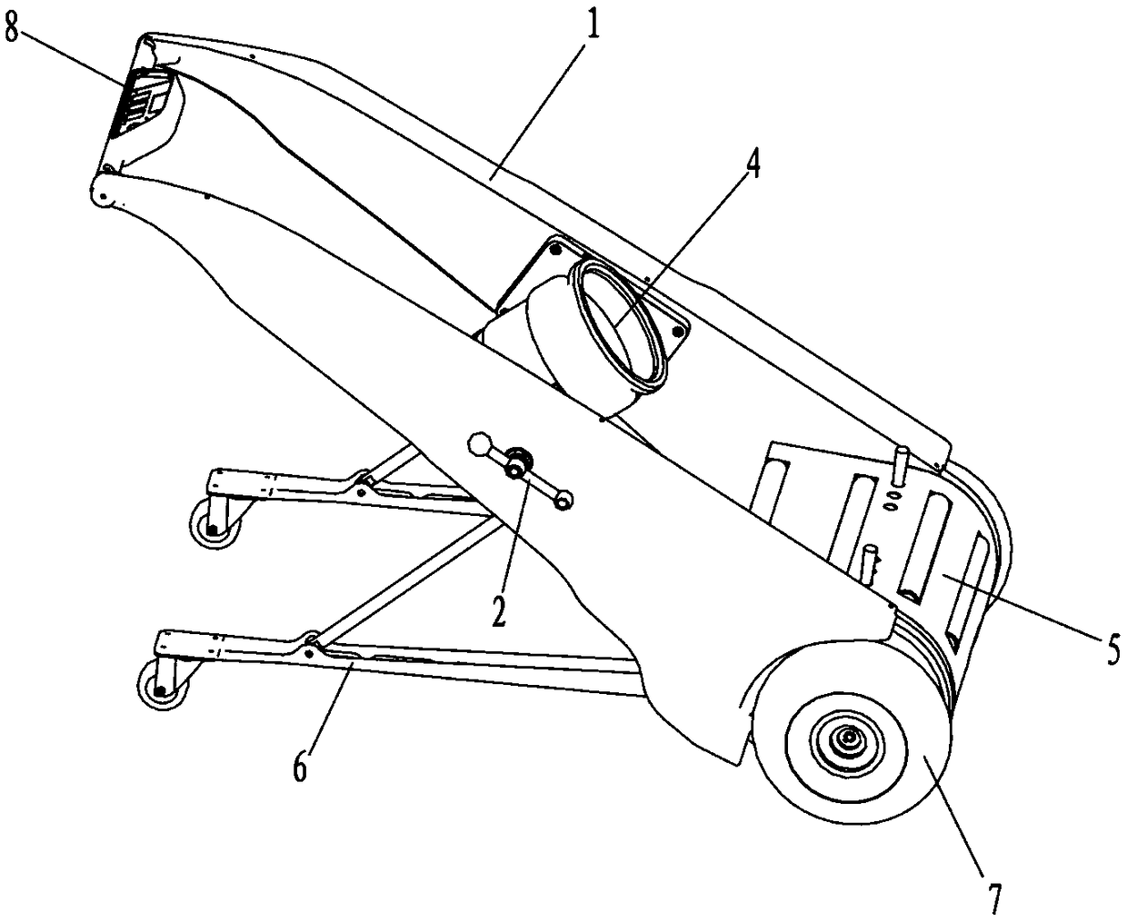
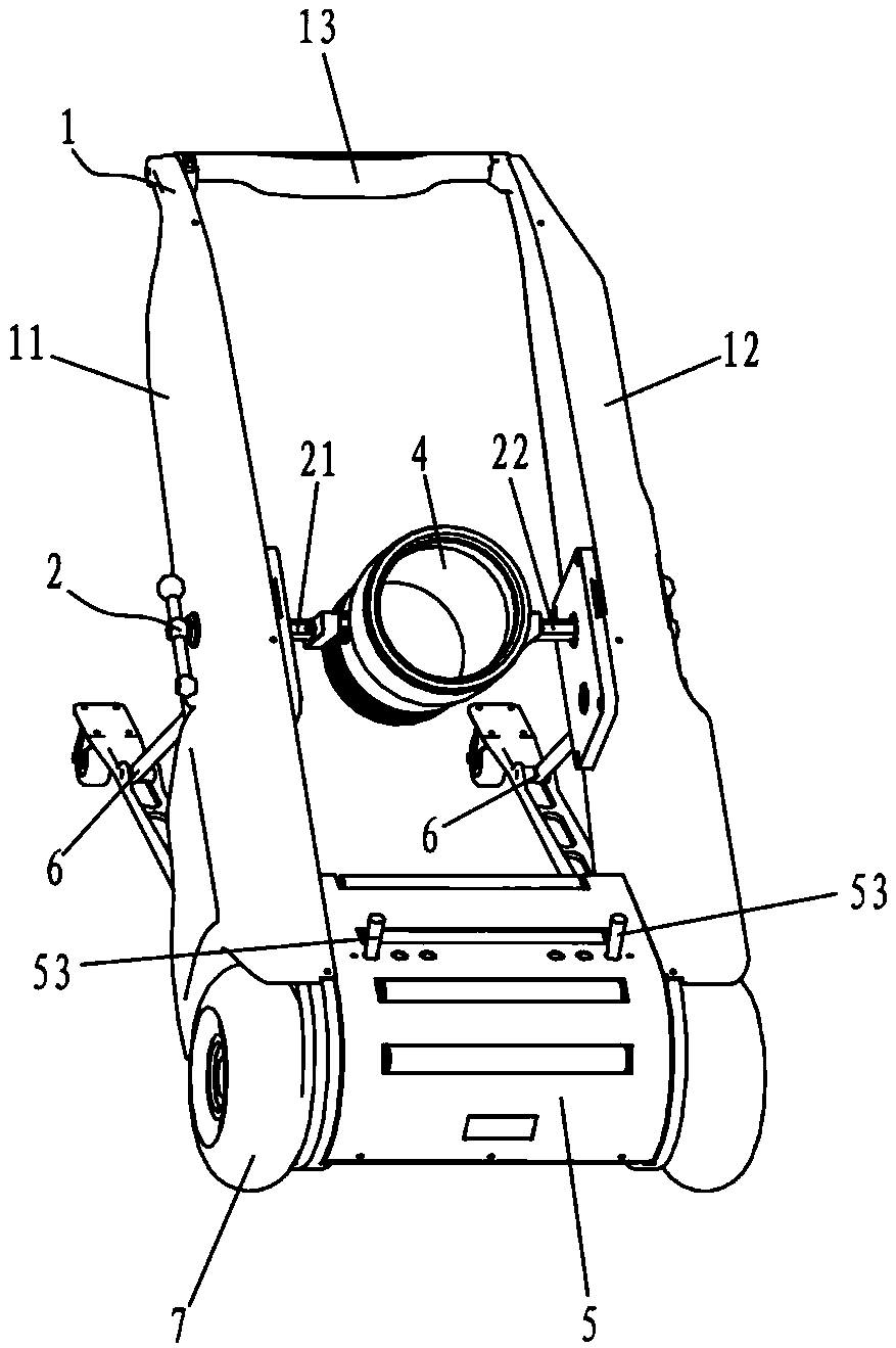
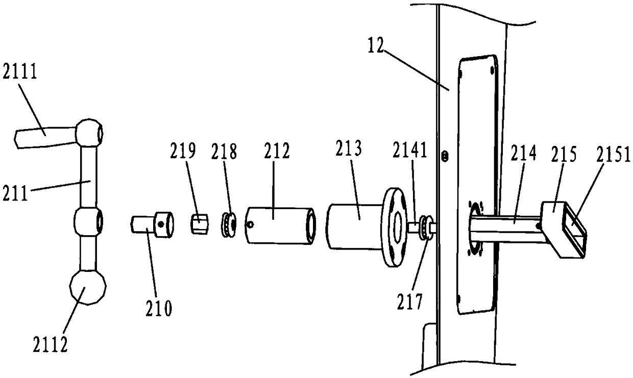
[0040] to combine Figure 1 to Figure 10 As shown, a hose laying and recovery equipment according to an embodiment of the present invention is schematically shown, which includes a frame assembly 1, a self-locking clamping mechanism 2 and a winding mechanism 3 arranged in the middle of the frame assembly 1, The quick connector 4 connected with the self-locking clamping mechanism 2, the water squeeze guide mechanism 5 arranged at the bottom of the frame assembly 1, the walking mechanism 7 arranged on both sides of the bottom of the frame assembly 1 and the connection with the frame assembly 1 The middle part is connected with the hose lifting and unloading mechanism 6 whic...


PUM


Abstract

The invention relates to the field of fire-fighting emergency devices, and particularly discloses a water band laying and recovering device which comprises a frame component, a self-locking clamping mechanism, a take-up mechanism, a rapid connector, a water extrusion guide mechanism, traveling mechanisms and a water band lifting and loading mechanism. The self-locking clamping mechanism and the take-up mechanism are arranged in the middle of the frame component, the rapid connector is connected with the self-locking clamping mechanism, a water extrusion guide mechanism is arranged on the lowerportion of the frame component, the traveling mechanisms are arranged on two sides of the bottom of the frame component, the water band lifting and loading mechanism is connected with the middle of the frame component, the water band lifting and loading mechanism and the frame component form a triangle supporting structure, the self-locking clamping mechanism comprises a left clamping arm and a right clamping arm, clamping heads are arranged at the opposite ends of the left clamping arm and the right clamping arm, the rapid connector is clamped between the clamping heads, the take-up mechanism comprises a take-up driving motor and a transmission component, the transmission component comprises a driving part and a driven part, the driving part is arranged on an output shaft of the take-updriving motor, the driven part is arranged on the self-locking clamping mechanism, the take-up driving motor drives the driving part to rotate, so that the driven part drives the rapid connector to rotate, and take-up and pay-off of a water band is completed.

Description

technical field [0001] The invention relates to the field of fire-fighting and emergency equipment, in particular to a hose laying and recovery equipment. Background technique [0002] At present, in fire rescue and drainage operations, the laying and recycling of hoses still rely on a lot of human intervention. However, for hoses with large diameters (6 inches and above), the weight of the hose itself is relatively high. Therefore, the intensity of human labor is extremely high when laying the hose, especially after the drainage operation is completed. The physical demands of rescuers after drainage operations are a challenge. [0003] In addition, in the existing rescue equipment, the winch is placed on the vehicle, the laying of the hose needs to be manually dragged and one winch equipment can only wind up one roll of hose, which leads to the use efficiency and reusability of the equipment, and the cost of the equipment. The flexibility and applicability are not high, w...

Claims


Application Information

Patent Timeline
Patent Type & Authority Applications(China)
IPC IPC(8): B65H75/40B65H75/44
CPCB65H75/403B65H75/44
Inventor 张增荣王珺吴家盛
Owner 广州多钛克机械科技有限公司
Why Eureka
Try Eureka