Electric furnace flip type counter-rotating quenching structure

A flip-type, electric furnace technology, applied in the direction of quenching device, furnace, furnace type, etc., can solve the problems of inconvenient material feeding and automatic unloading, and achieve the effect of convenient unloading, convenient connection, and guaranteed stability.

Active Publication Date: 2020-04-17
宁国市挚友合金钢材料有限公司
View PDF8 Cites 0 Cited by
  • Summary
  • Abstract
  • Description
  • Claims
  • Application Information

AI Technical Summary

Problems solved by technology

[0004] The purpose of the present invention is to overcome the deficiencies of the prior art, to meet the actual needs, and to provide a flip-type counter-rotating quenching structure of the electric furnace, which mainly solves the problem that the internal quenching structure of the existing electric furnace is inconvenient for material lifting and automatic unloading

Method used


Image

  • Electric furnace flip type counter-rotating quenching structure
  • Electric furnace flip type counter-rotating quenching structure
  • Electric furnace flip type counter-rotating quenching structure

Examples


Embodiment 1

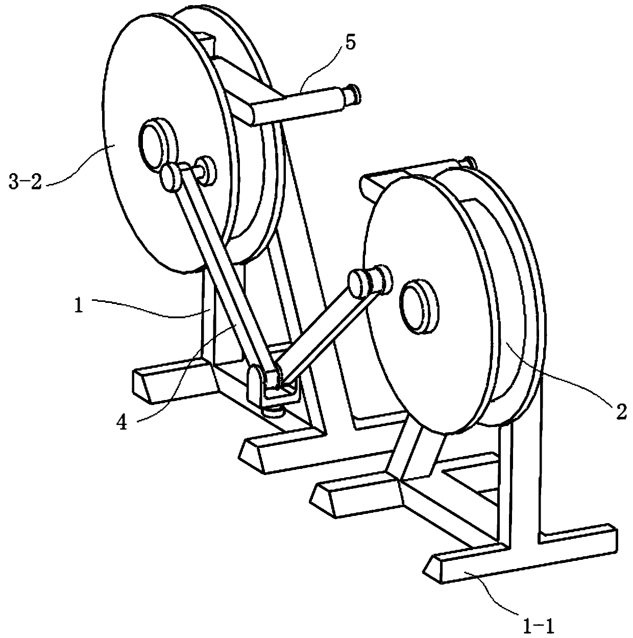
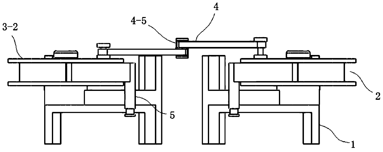
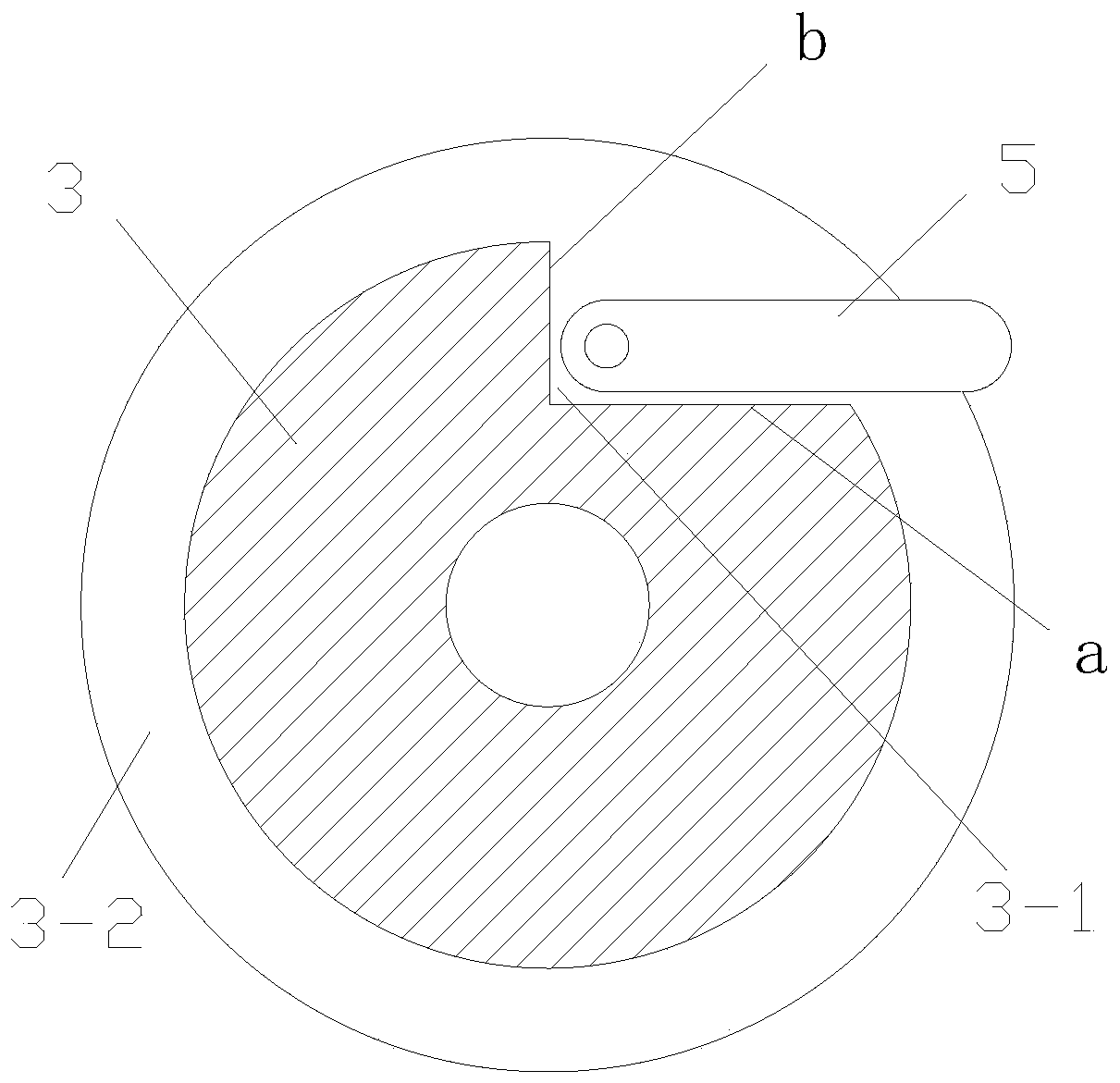
[0027] Such as Figure 1-2 Shown is an electric furnace flip-type counter-rotating quenching structure, including a bracket 1, and also includes a set of counter-rotating structures 2 and a driving motor arranged on the same side of the bracket 1. The counter-rotating structure 2 is composed of two counter-rotating wheels 3 and counter-rotating The connecting rod mechanism 4 between the rotating wheels and the turning material lifting rod 5 arranged on the counter rotating wheels 3 constitute, the driving motor is connected with the connecting rod mechanism 4, the counter rotating wheels 3 are vertically spaced apart and the surface of the counter rotating wheels is connected with the connecting rod. The rod mechanism 4 is connected, and the overturning lifting rod 5 is arranged around the counter-rotating wheel 3 and is connected in rotation with the counter-rotating wheel 3. The driving motor is connected with the middle part of the link mechanism 4 and drives the counter-rot...


PUM


Abstract

The invention relates to an electric furnace structure, and concretely relates to an electric furnace roll-over disrotatory quenching structure, which can mainly solve the problems of inconvenient material lift and automatic discharging of an internal quenching structure of the current electric furnaces. The quenching structure comprises a support, and also comprises a set disrotatory structure and a driving motor arranged at a same side of the support, and the disrotatory structure is formed by two disrotatory rollers and a link mechanism between two disrotatory rollers and a roll-over material lift rod arranged at the disrotatory roller. A traditional sander roller almost employs belt transmission to drive horizontal movement, the disrotatory roller having a simple and reliable structure, the link mechanism and the roll-over material lift rod realize the material lift and automatic discharging functions during a workpiece quenching process, compared with the current complex materiallift machines, the structure cost is reduced, a slip face is arranged at the roll-over material lift rod, when an upper half part face upwardly, the material lift function is realized, when a lower half part face downwardly, and automatic discharging is realized.

Description

technical field [0001] The invention relates to an electric furnace structure, in particular to an electric furnace flip-type counter-rotating quenching structure. Background technique [0002] The purpose of quenching is to transform supercooled austenite into martensite or bainite to obtain martensite or bainite structure, and then cooperate with tempering at different temperatures to greatly improve the strength, hardness and wear resistance of the steel. properties, fatigue strength and toughness, etc., so as to meet the different requirements of various mechanical parts and tools. In addition, special physical and chemical properties such as ferromagnetism and corrosion resistance of some special steels can also be satisfied through quenching. [0003] The traditional electric furnace is composed of furnace bottom support, heating furnace body, mobile quenching water tank car, ventilation mechanism, material basket lifting mechanism and electric (temperature) control sy...

Claims


Application Information

Patent Timeline
Patent Type & Authority Patents(China)
IPC IPC(8): C21D1/63C21D9/00
CPCC21D1/63C21D9/0018C21D9/0062
Inventor 王青云
Owner 宁国市挚友合金钢材料有限公司
Why Eureka
Try Eureka