Gas extraction drilling convenient-injection-type hole sealing device and method

A technology of gas drainage and hole sealer, which is applied in the direction of gas discharge, sealing/isolation, mining equipment, etc. It can solve the problems that the mixing effect of the sealing agent is difficult to guarantee, the internal structure and operation method are complicated, and it is unfavorable for underground workers to use it. , to achieve the effect of simple structure, low cost and low cost

Inactive Publication Date: 2018-11-16
CHINA UNIV OF MINING & TECH
View PDF8 Cites 7 Cited by
  • Summary
  • Abstract
  • Description
  • Claims
  • Application Information

AI Technical Summary

Problems solved by technology

Because the device uses the control part to inject the sealing agent into the air bag, its internal structure and operation method are very complicated, which is not conducive to the use of underground workers, and the manufacturing cost should be high
[0006] Furthermore, a multi-capsule hole-sealing device and method thereof (CN106930720A) for underground drilling in coal mines is also only applicable to the sealing of ordinary holes, and because the sealing agent is mixed by using a wire to rotate the trigger rod, If the screw is rusted or the screw is too tight, the thread is difficult to turn the screw, and the thread is easy to break, and the sealing agent mixing effect is difficult to guarantee

Method used


Image

  • Gas extraction drilling convenient-injection-type hole sealing device and method
  • Gas extraction drilling convenient-injection-type hole sealing device and method
  • Gas extraction drilling convenient-injection-type hole sealing device and method

Examples


Embodiment Construction

[0029] In order to make the objectives, technical solutions, and advantages of the embodiments of the present invention clearer, the technical solutions in the embodiments of the present invention will be described clearly and completely in conjunction with the accompanying drawings in the embodiments of the present invention. Obviously, the described embodiments It is a part of the embodiments of the present invention, but not all the embodiments. Based on the embodiments of the present invention, all other embodiments obtained by those of ordinary skill in the art without creative work shall fall within the protection scope of the present invention.

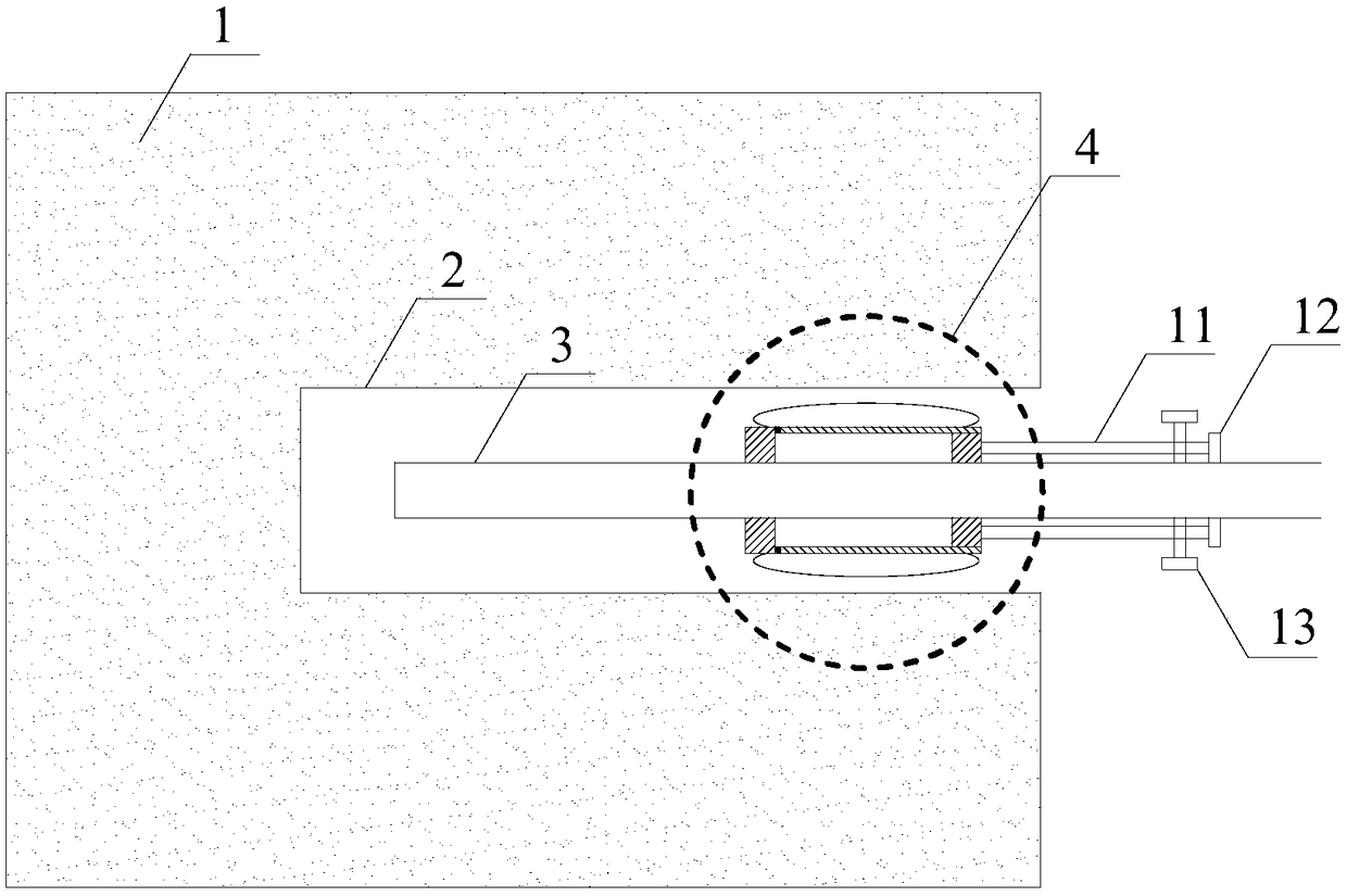
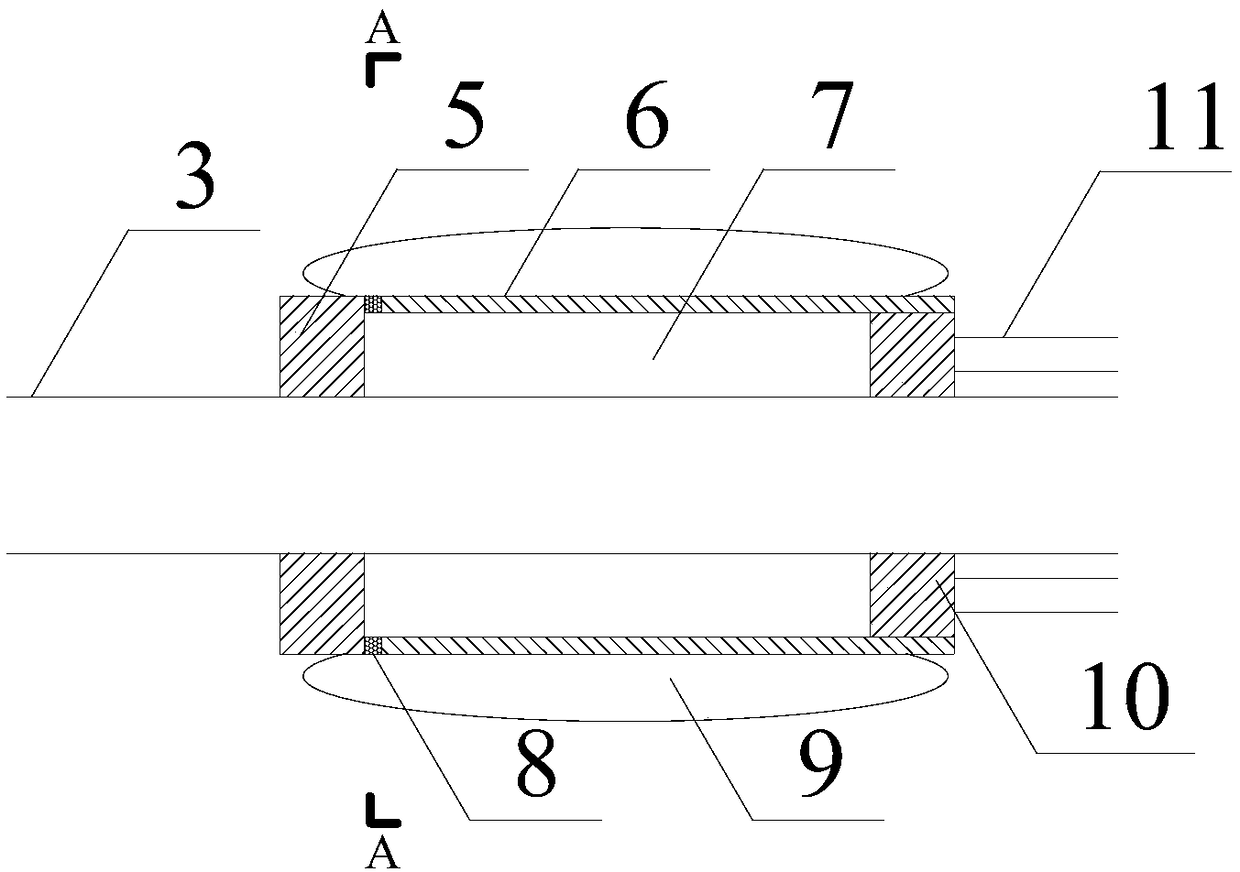
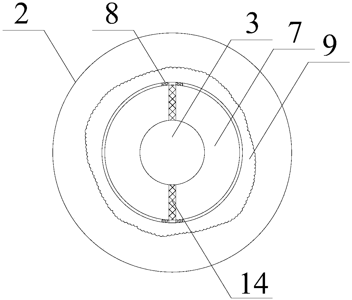
[0030] Figure 1 to Figure 4 Shows a schematic structural diagram of a preferred embodiment of the present invention. In the figure, a convenient injection-type plug for gas drainage drilling is mainly composed of a front baffle 5, a material chamber 7, a reaction airbag 9 and an extrusion The front baffle 5 is fixed at the front...


PUM


Abstract

The invention provides a gas extraction drilling convenient-injection-type hole sealing device which is mainly composed of a front baffle, a material chamber, a reaction air bag and an extrusion piston. The front baffle is fixed to the front end of the material chamber, the extrusion piston is mounted in the material chamber from the rear end in a sealed mode, and the tail end of the extrusion piston is fixedly connected with a piston rod; a penetrating hole communicating mutually and matched with an extraction pipe in outer diameter is formed in the middle of the front baffle, the material chamber, the extrusion piston and the piston rod; the extraction pipe is mounted in the penetrating hole in a sealed mode; the reaction air bag is arranged on the periphery of the material chamber, anda connecting hole communicating with the reaction air bag is formed in the position, close to the front baffle, of the bottom end of the outer wall of the material chamber; and a plug is mounted at the connecting hole, the material chamber is divided into two material chamber bodies by a partition plate mounted in the middle, and the two material chamber bodies are loaded with a polyurethane A material and a polyurethane B material. According to the gas extraction drilling convenient-injection-type hole sealing device, the hole sealing materials can react at the predetermined hole sealing position in drilled hole, the operation steps are simple, and the influence of manual operation error on the hole sealing effect can be greatly reduced.

Description

Technical field [0001] The invention relates to a convenient injection type hole sealing device for gas drainage drilling and a hole sealing method, and belongs to the related technical field of gas drainage and sealing in underground coal mines. Background technique [0002] The coal mines currently mined in my country are mostly high-gas mines, so the effect of underground gas drainage greatly affects the mine production efficiency. The hole sealing effect of drainage boreholes is one of the important factors affecting the effect of underground gas drainage. Therefore, efficient sealing measures are one of the indispensable technologies for efficient production of coal mines today. [0003] The traditional drainage hole sealing technology used in our country mostly uses polyurethane AB material to react in advance outside the hole, and then plug it into the drainage hole for plugging. Since the sealing material has already started to react outside the drilling, this method requi...

Claims


Application Information

Patent Timeline
Patent Type & Authority Applications(China)
IPC IPC(8): E21B33/12E21F7/00
CPCE21B33/12E21B33/1208E21F7/00
Inventor 林柏泉王正杨威刘统
Owner CHINA UNIV OF MINING & TECH
Why Eureka
Try Eureka