
Demand calculation method for smart electric meters

A calculation method and technology of smart meters, which are applied in the measurement of electrical variables, measurement devices, complex mathematical operations, etc., can solve problems such as processing, and achieve the effect of reasonable and accurate calculation methods and convenient calculation.

Active Publication Date: 2018-11-16
NINGBO SANXING INTELLIGENT ELECTRIC
View PDF7 Cites 2 Cited by
  • Summary
  • Abstract
  • Description
  • Claims
  • Application Information

AI Technical Summary

Problems solved by technology

However, this invention only optimizes the demand calculation in the case of power-off and power-on, but does not deal with the clock calibration of the smart meter and the demand calculation in the case of periodic changes in demand, so it is necessary to further improve the demand of the smart meter calculation method

Method used


Image

  • Demand calculation method for smart electric meters
  • Demand calculation method for smart electric meters
  • Demand calculation method for smart electric meters

Examples


Embodiment 1

[0055] The demand calculation after clock calibration and demand period change using the interval-based demand calculation method is as follows:

[0056] Time calibration within the demand period T:

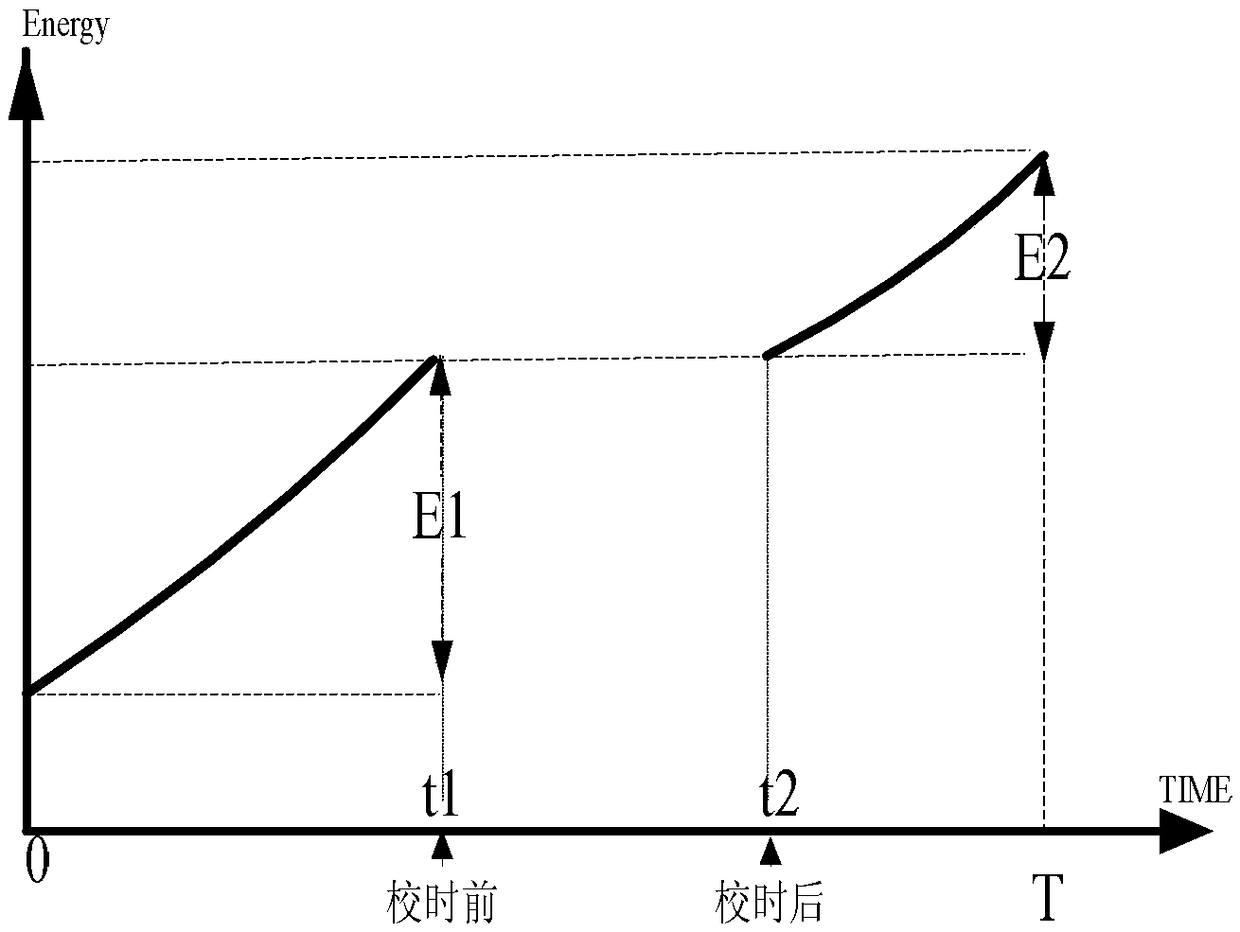
[0057] Such as figure 2 As shown, the demand cycle is [0, T), the time t1 before clock calibration is less than the time t2 after calibration, that is, the clock is adjusted backwards, t1 and t2 are both within the demand cycle T, and in [0, T) The electricity accumulated in the period is E1, and the electricity accumulated in [t2, T) is E2, then the demand period is [0, T) and the demand P=E2 / T.

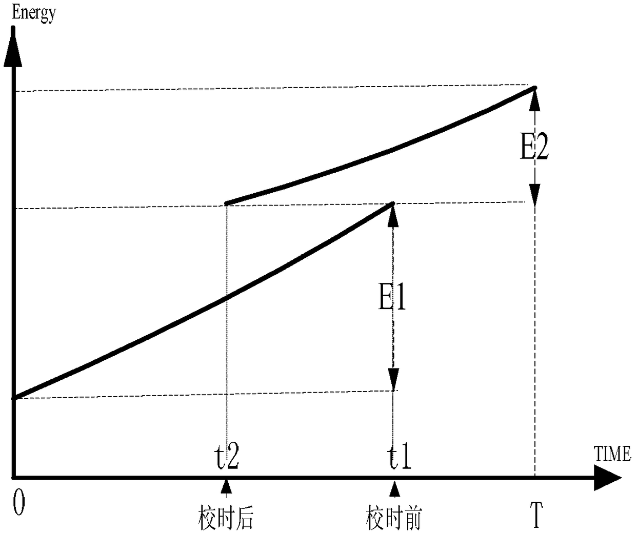
[0058] Such as image 3 As shown, the demand period is [0, T), the time t1 before clock calibration is greater than the time t2 after calibration, that is, the clock is adjusted forward, and both t1 and t2 are within the demand period T, in [0, t1 ) is E1, and the accumulated electricity in [t2, T) is E2, then the demand period is [0, T) and the demand P=E2 / T.

[0059] Time calibr...

Embodiment 2

[0068] The demand calculation after clock calibration and demand period change using the slipping demand calculation method is as follows:

[0069] Time calibration within slip cycle T1:

[0070] Such as Figure 8 As shown, the slip cycle is T1, the number of slips is N=2, then the second demand cycle is T2=2T1, the time t1 before the clock calibration is less than the time t2 after the calibration, that is, the clock is adjusted backwards, and t1 and t2 are both in the slip cycle [2T1, 3T1), the accumulated electricity in [0, T1) is E1, the accumulated electricity in [T1, 2T1) is E2, and the accumulated electricity in [2T1, t1) is E3, the accumulated electricity in [t2, 3T1) is E4, and the accumulated electricity in [3T1, 4T1) is E5, then the demand P1 of the second demand cycle [0, 2T1) = 0; the second demand The demand P2 of the quantity period [T1, 3T1) = E4 / 2T1; the demand P3 of the second demand period [2T1, 4T1] = (E4+E5) / 2T1;

[0071] Such as Figure 9 As shown, th...


PUM


Abstract

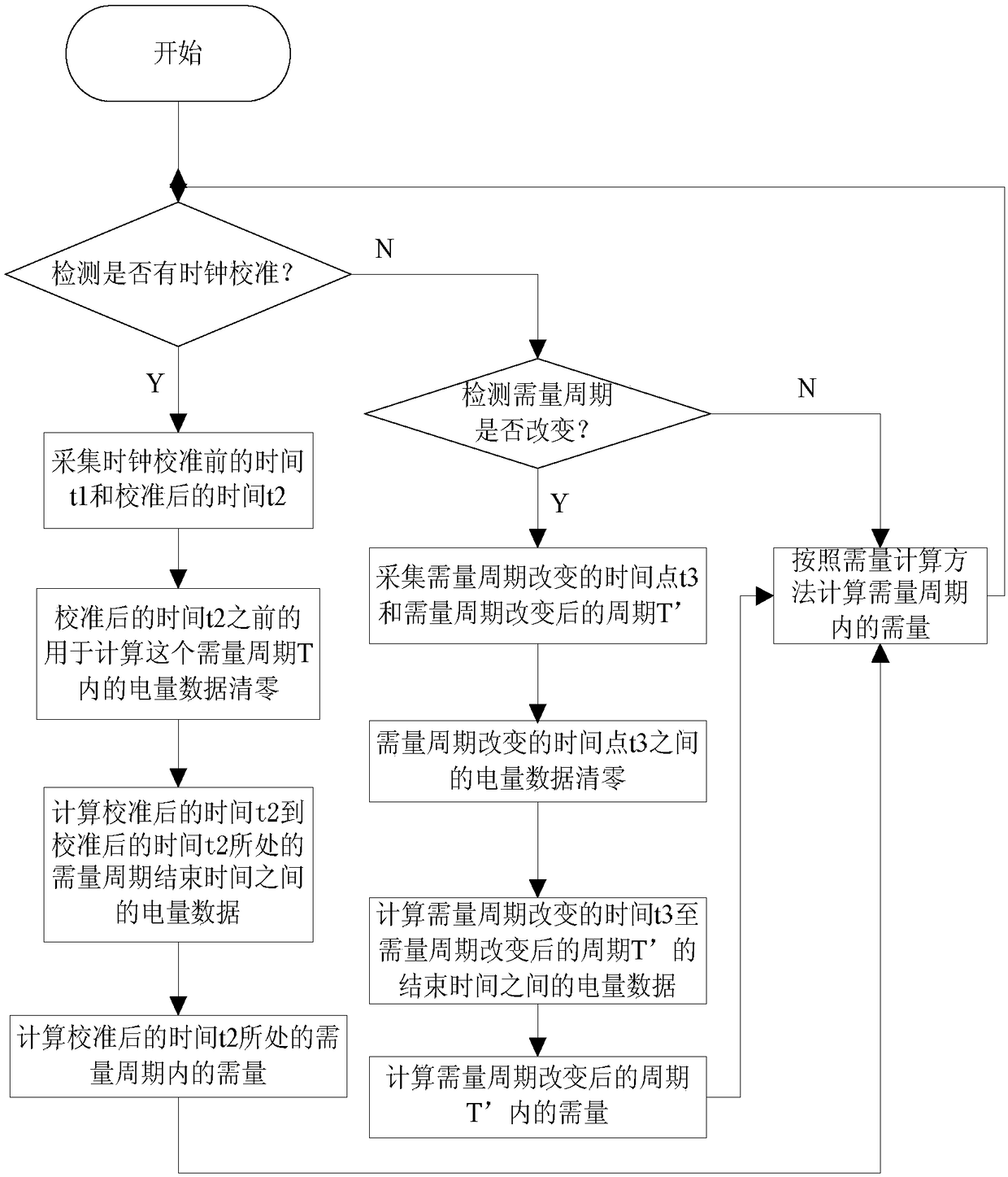
The invention relates to a demand calculation method for smart electric meters. The demand calculation method is characterized by including the steps of (1), detecting whether needing to calibrate clock or changing demand interval of the smart electric meters, if needing to calibrate clock, then going to the step (2), if needing to change the demand interval, then going to the step (4); (2), acquiring the time t1 before clock calibration and the time t2 after calibration; (3), clearing electric quantity data before the time t2 after calibration and calculating the demand within the demand interval of the time t2 after calibration; (4), acquiring the time point t3 at where the demand interval changes and the interval T' after the demand interval changes; (5), clearing electric quantity data before the time point t3 at where the demand interval changes, and calculating the demand within the interval T' after the demand interval changes, and going to the step (6), calculating the demand,within the demand interval, of the smart electric meters on the premise of without any change by means of a demand calculation method. The demand calculation method is much reasonable and accurate.

Description

technical field [0001] The invention relates to the field of smart electric meters, in particular to a method for calculating the demand of the smart electric meter. Background technique [0002] Smart meters are one of the basic equipment for data collection in smart grids (especially smart distribution networks). Foundation. Demand is an important function in smart meters. In a specified time period, the maximum average power measured in the demand cycle is called the maximum demand of electric energy. The measurement of the maximum demand of electric energy is of great significance to the electric energy management of power lines or power networks. For the power supply related departments: it is beneficial to the reasonable adjustment of the line and optimal scheduling work; for the user, knowing the maximum demand of the line and adjusting the load distribution can make the system stable without increasing the capacity of the transformer. Go to the source and open the...

Claims


Application Information

Patent Timeline
Patent Type & Authority Applications(China)
IPC IPC(8): G06F17/18G01R22/10
CPCG06F17/18G01R22/10
Inventor 应必金应碧锋
Owner NINGBO SANXING INTELLIGENT ELECTRIC
Learn More