
electrical connector

A technology for electrical connectors and terminals, which is applied in the direction of connection, components and circuits of connecting devices, can solve the problems of no downward insertion of pins, limited space for pin insertion, affecting the electrical connection between the electrical connector and the chip module, etc. , to achieve the effect of ensuring stable contact

Active Publication Date: 2020-03-24
DEYI PRECISION ELECTRONIC IND CO LTD PANYU
View PDF3 Cites 0 Cited by
  • Summary
  • Abstract
  • Description
  • Claims
  • Application Information

AI Technical Summary

Problems solved by technology

[0003] However, in order to meet higher requirements for signal transmission, the arrangement of the terminals becomes more and more dense, and the insertion space reserved for the pins of the chip module in the receiving grooves is very limited, so two adjacent receiving grooves will be Part of the partition between them is dug out to form a space for the pins of the chip module to be inserted, so that the two adjacent receiving grooves communicate with each other, so that the receiving grooves do not have the function of guiding the pins to be inserted downward. Therefore, During the insertion process, the pins will inevitably appear crooked and unable to work normally, thus affecting the stable electrical connection between the electrical connector and the chip module

Method used


Image

  • electrical connector
  • electrical connector
  • electrical connector

Examples


Embodiment Construction

[0028] In order to facilitate a better understanding of the purpose, structure, features, and effects of the present invention, the present invention will now be further described in conjunction with the accompanying drawings and specific embodiments.

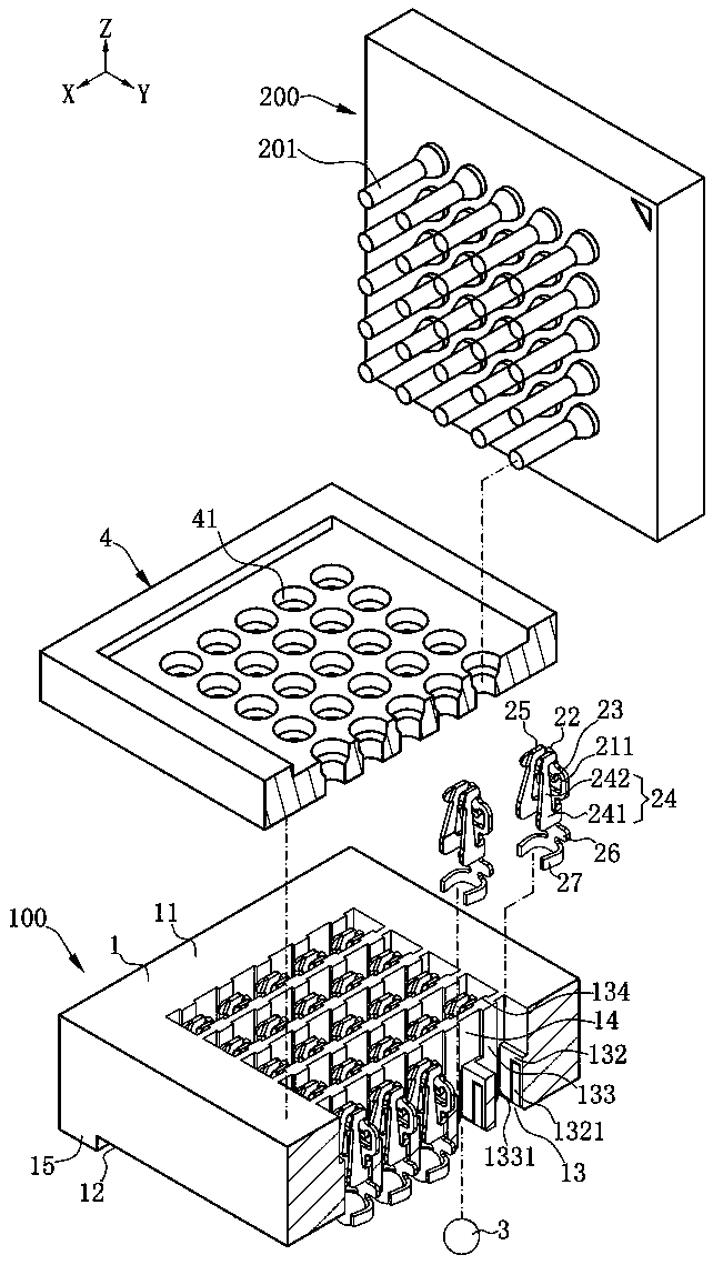
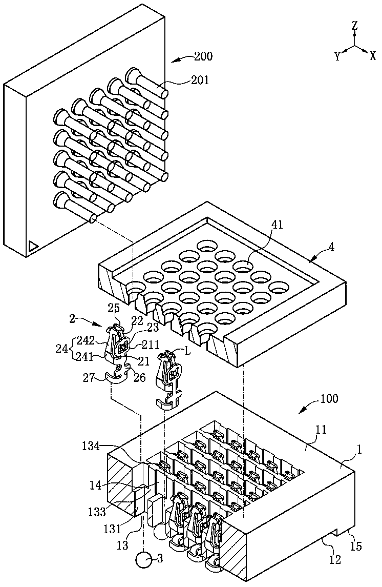
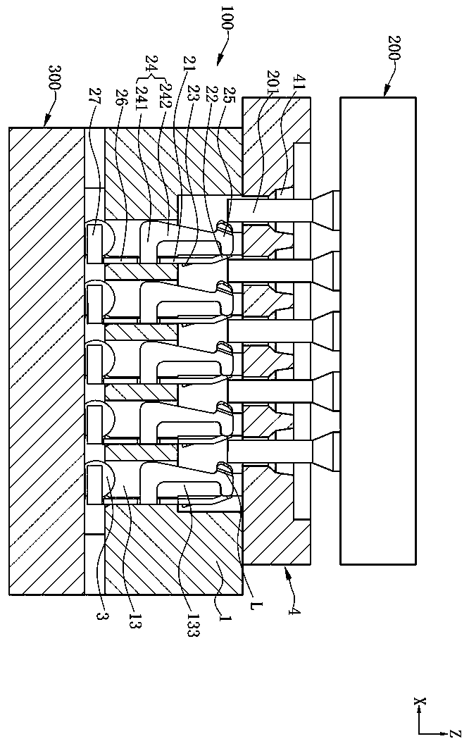
[0029] Such as Figure 1 to Figure 7 Shown is an embodiment of the electrical connector of the present invention. The electrical connector 100 of the present invention is used to electrically connect a chip module 200 to a circuit board 300. The chip module 200 has a plurality of pins 201. The electrical connector 100 includes An insulating body 1 , a plurality of terminals 2 accommodated in the insulating body 1 and an upper cover 4 located above the insulating body 1 . The upper cover 4 is used to receive the chip module 200 , and is provided with a plurality of through holes 41 passing through the upper cover 4 up and down for receiving the pins 201 . Described loam cake 4 is by a driving device (driving device is not drawn...


PUM


Abstract

The invention discloses an electrical connector for electrically connecting a chip module with a plurality of pins, which is characterized in that it comprises: an insulating body provided with a plurality of storage slots, and a There is a space for the two to communicate with each other; a plurality of terminals are correspondingly accommodated in the receiving groove, each terminal includes a base and two arms extending upward from the base, and the two arms have two clamping parts and two clamping parts The base part is bent forward and extends away from each other to form two guide parts, and an inclined part is formed by bending forward and extending upward from the base part. The front side of the inclined part has a contact surface, the contact surface and two clamping parts Used to clamp the pins together, the rear side of the inclined part has a guide surface, the top of the guide surface is higher than the bottom surface of the space; when the chip module is installed, the two adjacent terminals in the front and rear direction, the front terminal The guide surface first guides the pins to be inserted downwards, and the guide part of the latter terminal guides the pins to move horizontally.

Description

technical field [0001] The invention relates to an electrical connector, in particular to an electrical connector for inserting pins of a chip module. Background technique [0002] An electrical connector commonly used in the industry is used to electrically connect chip modules with multiple pins. The electrical connector has an insulating body, an upper cover on the insulating body, and multiple terminals accommodated in the insulating body. The insulating body is provided with a plurality of accommodating grooves arranged at intervals corresponding to accommodating a plurality of the terminals. The terminal includes: a base, which cooperates with the receiving groove to hold the terminal, is bent from opposite sides of the base and extends upward to form two arm portions, and the two arm portions are respectively provided with a contact portion and a connection A guide portion of the contact portion forms a clamping space between the two contact portions of the two arm p...

Claims


Application Information

Patent Timeline
Patent Type & Authority Patents(China)
IPC IPC(8): H01R12/71H01R13/11H01R13/631H01R33/76
CPCH01R12/716H01R13/111H01R13/631H01R33/76H01R12/7076
Inventor 黄常伟
Owner DEYI PRECISION ELECTRONIC IND CO LTD PANYU
Learn More